
A5
| Overview of fitting locations |
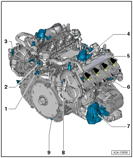
| Part 1 |

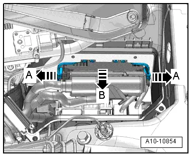
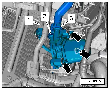
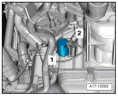
| 1 - | Secondary air pump motor -V101- |
| q | Fitting location → Fig. |
| q | Removing and installing → Rep. gr.26 |
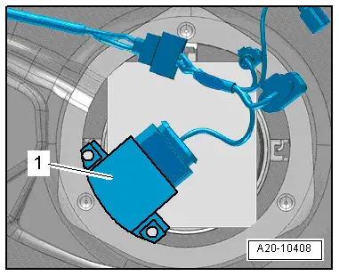
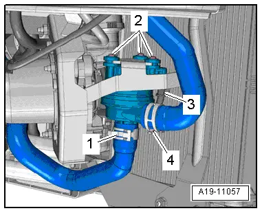
| 2 - | Continued coolant circulation pump -V51- |
| q | Fitting location → Fig. |
| q | Removing and installing → Rep. gr.19 |
| 3 - | Throttle valve module -J338- |
| q | Including throttle valve drive for electric throttle -G186-, throttle valve drive angle sender 1 for electric throttle -G187- and throttle valve drive angle sender 2 for electric throttle -G188- |
| q | Removing and installing → Chapter |
| q | After renewing, perform Adaption in Guided Functions → Vehicle diagnostic tester |
| 4 - | Lambda probe -G39- |
| q | (Before catalytic converter) with Lambda probe heater -Z19- |
| q | Exploded view → Chapter |
| 5 - | Lambda probe after catalytic converter -G130- |
| q | With Lambda probe 1 heater after catalytic converter -Z29- |
| q | Exploded view → Chapter |
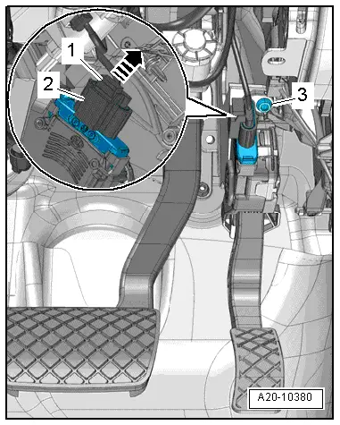
| 6 - | Accelerator pedal module |
| q | With accelerator position sender -G79- / accelerator position sender 2 -G185- |
| q | Fitting location → Fig. |
| q | Removing and installing → Rep. gr.20 |
| 7 - | Engine control unit -J623- |
| q | Fitting location → Fig. |
| q | Removing and installing → Chapter |
| 8 - | Lambda probe 2 after catalytic converter -G131- |
| q | With Lambda probe 2 heater after catalytic converter -Z30- |
| q | Exploded view → Chapter |
| 9 - | Lambda probe 2 -G108- |
| q | (Before catalytic converter) with Lambda probe heater 2 -Z28- |
| q | Exploded view → Chapter |
| 10 - | Throttle valve module 2 -J544- |
| q | With throttle valve drive 2 -G296-, angle sender 1 for throttle valve drive 2 -G297- and angle sender 2 for throttle valve drive 2 -G298- |
| q | Removing and installing → Chapter |
| q | After renewing, perform Adaption in Guided Functions → Vehicle diagnostic tester |
| 11 - | Brake vacuum pump -V192- |
| 12 - | Secondary air pump motor 2 -V189- |
| q | Fitting location → Fig. |
| q | Removing and installing → Rep. gr.26 |
| 13 - | Intake air temperature sender -G42- / intake manifold pressure sender -G71- |

| 1 - | Injector, cylinder 1 -N30- |
| q | Exploded view → Chapter |
| 2 - | Ignition coil 1 with output stage -N70- |
| q | Removing and installing → Chapter |
| 3 - | Injector, cylinder 2 -N31- |
| 4 - | Ignition coil 2 with output stage -N127- |
| 5 - | Injector, cylinder 3 -N32- |
| 6 - | Ignition coil 3 with output stage -N291- |
| 7 - | Injector, cylinder 4 -N33- |
| 8 - | Ignition coil 4 with output stage -N292- |
| 9 - | Exhaust camshaft control valve 1 -N318- |
| 10 - | Camshaft control valve 1 -N205- |
| 11 - | Knock sensor 2 -G66- |
| q | Removing and installing → Chapter |
| 12 - | Secondary air inlet valve -N112- |
| 13 - | Knock sensor 4 -G199- |
| q | Removing and installing → Chapter |
| 14 - | Camshaft control valve 2 -N208- |
| 15 - | Exhaust camshaft control valve 2 -N319- |
| 16 - | Ignition coil 8 with output stage -N326- |
| 17 - | Injector, cylinder 8 -N86- |
| 18 - | Ignition coil 7 with output stage -N325- |
| 19 - | Injector, cylinder 7 -N85- |
| 20 - | Ignition coil 6 with output stage -N324- |
| 21 - | Injector, cylinder 6 -N84- |
| 22 - | Ignition coil 5 with output stage -N323- |
| 23 - | Injector, cylinder 5 -N83- |
| 24 - | Knock sensor 3 -G198- |
| q | Removing and installing → Chapter |
| 25 - | Intake manifold flap valve -N316- |
| 26 - | Knock sensor 1 -G61- |
| q | Removing and installing → Chapter |
| 27 - | Fuel pressure sender -G247- |
| q | Fitting location → Fig. |
| q | Removing and installing → Chapter |

| 1 - | Coolant temperature sender -G62- |
| q | Removing and installing → Rep. gr.19 |
| 2 - | Intake manifold flap potentiometer 2 -G512- |
| 3 - | Intake manifold flap potentiometer -G336- |
| 4 - | Oil pressure switch -F22- |
| q | Removing and installing → Rep. gr.17 |
| 5 - | Oil temperature sender -G8- |
| q | Removing and installing → Rep. gr.17 |
| 6 - | Activated charcoal filter solenoid valve 1 -N80- |
| 7 - | Fuel metering valve 2 -N402- |
| 8 - | Hall sender 2 -G163- |
| q | Removing and installing → Chapter |
| 9 - | Hall sender 4 -G301- |
| q | Removing and installing → Chapter |
| 10 - | Servotronic solenoid valve -N119- |
| q | Only on vehicles with hydraulic power steering |
| 11 - | Left electrohydraulic engine mounting solenoid valve -N144- |
| q | On engine mounting (left-side) |
| 12 - | Valve for oil pressure control -N428- |
| q | Fitting location → Fig. |
| q | Removing and installing → Rep. gr.17 |
| 13 - | Map-controlled engine cooling system thermostat -F265- |
| q | Removing and installing → Rep. gr.19 |
| 1 - | Oil pressure switch for reduced oil pressure -F378- |
| q | Removing and installing → Rep. gr.17 |
| 2 - | Fuel pressure sender for low pressure -G410- |
| 3 - | Sender 2 for secondary air pressure -G610- |
| q | Removing and installing → Rep. gr.26 |
| 4 - | Fuel metering valve -N290- |
| q | at high-pressure pump (right-side) |
| 5 - | Hall sender -G40- |
| q | Removing and installing → Chapter |
| 6 - | Hall sender 3 -G300- |
| q | Removing and installing → Chapter |
| 7 - | Right electrohydraulic engine mounting solenoid valve -N145- |
| q | On engine mounting (right-side) |
| 8 - | Sender 1 for secondary air pressure -G609- |
| q | Removing and installing → Rep. gr.26 |
| 9 - | Engine speed sender -G28- |
| q | Removing and installing → Chapter |
|
|
|
|
|
|
|
|
|
|
|
|