
A5
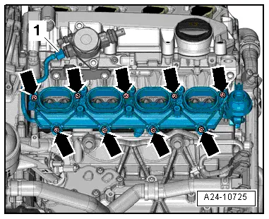
| Intake manifold (bottom section), fuel rail and injectors - exploded view |

| 1 - | Seals |
| q | Renew |
| 2 - | Intake manifold (bottom section) |
| q | Removing and installing → Chapter |
| 3 - | Seal |
| q | Renew if damaged |
| q | When renewing lever out with screwdriver |
| q | Press in by hand |
| 4 - | Bolt |
| q | 2.5 Nm |
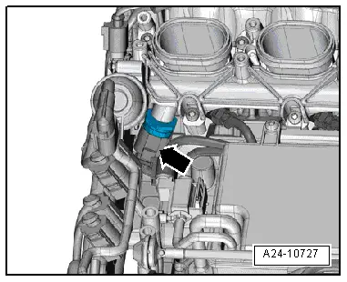
| 5 - | Intake manifold flap potentiometer |
| q | Cylinder bank 1 (right-side): intake manifold flap potentiometer -G336- |
| q | Cylinder bank 2 (left-side): intake manifold flap potentiometer 2 -G512- |
| q | Before removing, remove intake manifold (top section) |
| q | Adaption must be performed after this component has been renewed; use a vehicle diagnostic tester |
| 6 - | Bolt |
| q | 2.5 Nm |
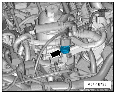
| 7 - | Vacuum unit |
| q | For intake manifold flaps |
| q | After renewing, check vacuum system for leaks → Chapter |
| 8 - | Screw plug |
| q | 25 Nm |
| 9 - | Fuel rail |
| q | Removing and installing → Chapter „Removing and installing injectors“ → Chapter |
| 10 - | Sleeve |
| 11 - | Retaining clip |
| q | For fuel rail |
| 12 - | Bolt |
| q | Tightening torque and sequence → Fig. |
| 13 - | High-pressure pipe |
 WARNING
|
| q | Reducing fuel pressure in high-pressure section of injection system → Chapter |
| q | Connections must not be damaged |
| q | Do not alter shape |
| q | Removing and installing → Chapter |
| q | Lubricate thread lightly with engine oil |
| q | 25 Nm |
| 14 - | Bolt |
| q | 9 Nm |
| 15 - | Bolt |
| q | 2.5 Nm |
| 16 - | Union nut |
| q | Lubricate thread lightly with engine oil |
| q | 25 Nm |
| 17 - | Seals |
| q | Renew |
| 18 - | Support ring |
| q | Renew |
| q | Via this support ring, the fuel rail exerts the clamping force that holds the injector in the cylinder head |
| 19 - | O-ring |
| q | Renew |
| q | Lubricate lightly with clean engine oil |
| 20 - | Spacer ring |
| q | Renew if damaged |
| 21 - | Injector |
| q | Removing and installing → Chapter |
| 22 - | Sealing element |
| q | Renew |
| 23 - | Combustion chamber ring seal |
| q | Renew |
| q | Do not apply grease or use any other lubricants |
|
|
|
|
|
|