| –
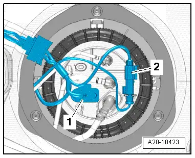
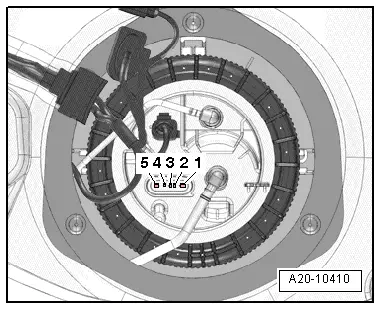
| Connect multimeter (resistance test) between contacts -2- and -4-. |
| Fuel gauge sender -G- installed: |
| l
| Sender at lower stop: approx. 280 Ω. |
| l
| Sender at upper stop: approx. 65 Ω. |

Note | t
| If the resistance is 0 Ω, there is a short circuit. If the resistance is ∞ Ω, there is an open circuit in the wiring. |
| t
| To test the maximum and minimum resistance values for „tank full“ and „tank empty“, remove the fuel delivery unit → Chapter and move the sender float all the way to its top or bottom position. |
| t
| The following values are obtained with the fuel gauge sender removed, due to the greater travel of the float arm: |
| Fuel gauge sender -G- removed: |
| l
| Sender at lower stop: approx. 288 Ω. |
| l
| Sender at upper stop: approx. 57 Ω. |
| –
| Connect multimeter (resistance test) between contacts -3- and -4-. |
| Fuel gauge sender -G- installed or removed: |
| l
| Sender in any position: approx. 340 Ω. |
| Installation is carried out in the reverse order; note the following: |
| –
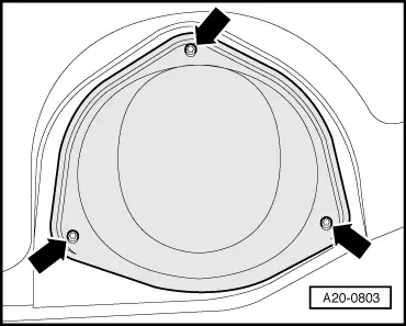
| Install cover for flange → Fig.. |
|
|
|