| –
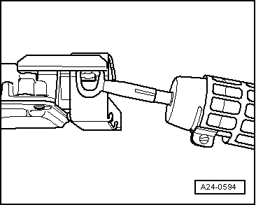
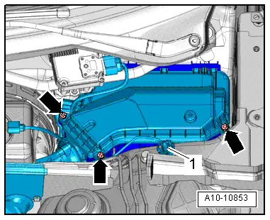
| The two shear bolts screwed into the engine control unit do not need to be heated. They can be removed without heating. |
| –
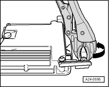
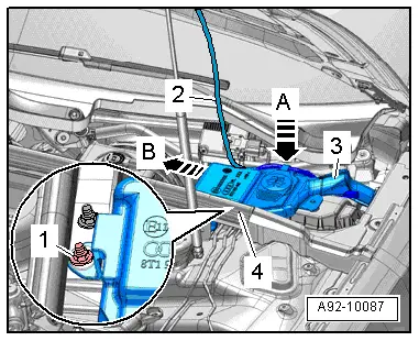
| Detach metal locking plate from control unit connectors. |
| –
| Release connectors on engine control unit and unplug connectors. |
| –
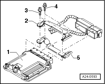
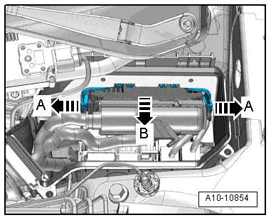
| Take out old engine control unit -J623- and install new engine control unit -J623-. |
| Installation is performed in the reverse sequence. |
| –
| After installation, the locking plate must be re-fitted on the engine control unit -J623-. |
| –
| Clean threaded holes for shear bolts to remove any residue from locking fluid. This can be done using a thread tap. |
| –
| Always use new shear bolts. |
| l
| Tightening torque for bolts securing cover of electronics box: 3.5 Nm. |
| After installing a new engine control unit, the following operation must be performed: |
| –
| Activate engine control unit via vehicle diagnostic, testing and information system -VAS 5051B- in “Guided Functions” mode, “Replace engine control unit”. |
|
|
|
 Note
Note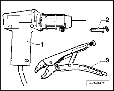
 WARNING