
A5
 Note
Note
|
 WARNING
 Caution
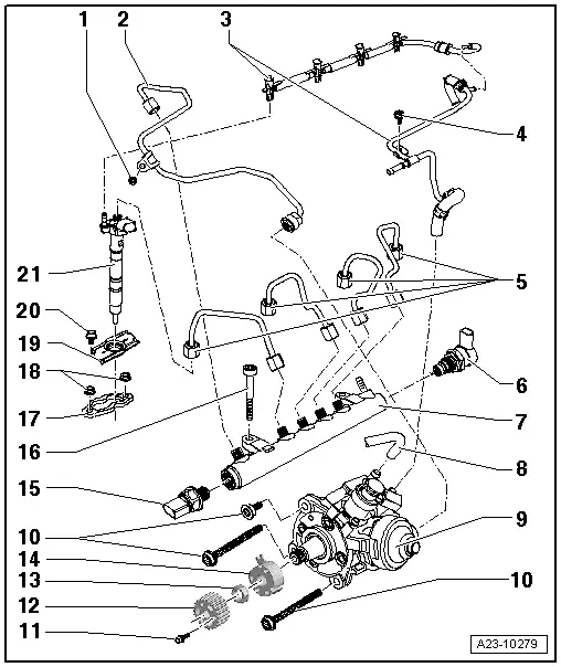
| 1 - | Bolt |
| q | 10 Nm |
| 2 - | High-pressure pipe |
| q | 25 Nm |
| q | Between high-pressure pump and fuel rail |
| 3 - | Fuel return lines |
| q | To fuel tank |
| q | Fuel return line must not be kinked, damaged or clogged |
| q | The fuel return lines must not be dismantled; if necessary they must be renewed complete with pressure retention valve |
| q | The pressure retention valve maintains a residual pressure of approx. 10 bar in the return lines |
| q | This residual pressure is required for the control function of the injectors |
| q | Checking pressure retention valve → Chapter |
| q | After replacement, engine must be run at idling speed for approx. 2 minutes to bleed fuel system. Then check fuel return lines for leaks |
| 4 - | Bolt |
| q | 10 Nm |
| 5 - | High-pressure pipes |
| q | 25 Nm |
| q | Between fuel rail and injectors |
| q | Do not interchange |
| q | Install free of stress |
| 6 - | Fuel pressure regulating valve -N276- |
| q | 80 Nm |
| q | Cannot be re-installed |
| q | Removing and installing → Chapter |
| 7 - | Fuel rail |
| q | Removing and installing → Chapter |
| 8 - | Fuel supply line |
| 9 - | High-pressure pump |
| q | With fuel metering valve -N290- (do not open) |
| q | After renewing, first fuel filling operation MUST be performed (it is important not to allow pump to run while it is still empty) → Chapter |
| q | Removing and installing → Chapter |
| 10 - | Bolt |
| q | 20 Nm |
| q | Turn long bolts 180° further |
| q | Turn short bolts 90° further |
| 11 - | Bolt |
| q | 20 Nm |
| 12 - | Toothed belt sprocket for high-pressure pump |
| 13 - | Nut |
| q | 95 Nm |
| 14 - | Hub |
| q | With sender wheel |
| q | Use counterhold tool -T10051- to loosen and tighten |
| q | To remove, use puller -T40064- |
| 15 - | Fuel pressure sender -G247- |
| q | 100 Nm |
| q | Removing and installing → Chapter |
| 16 - | Bolt |
| q | 22 Nm |
| 17 - | Clamping piece |
| q | If they are to be re-installed, the injectors and clamping pieces must always be re-fitted on the same cylinder. |
| q | When an injector is renewed, the corresponding clamping piece must be renewed at the same time |
| 18 - | Hexagon flange nut |
| q | For clamping piece |
| q | 10 Nm |
| 19 - | Cover for injector |
| 20 - | Bolt |
| q | 5 Nm |
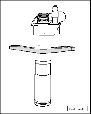
| 21 - | Injector |
| q | If they are to be re-installed, the injectors, high-pressure fuel pipes and clamping pieces must always be re-fitted in their original positions (i.e. on the same cylinder). |
| q | Removing and installing → Chapter |
|
|