audi Workshop Repair Guides

Audi Workshop Service and Repair Manuals

Engine control unit > < Injection system
Removing and installing high-pressure pump
Special tools and workshop equipment required
   
t  Locking pin -3242-
  W00-0293
t  Adapter -T40058-
  W00-10109
t  Locking pin -T40245-
  W00-10907
t  Counterhold tool -T40248-
Removing
–  Remove intake manifold → Chapter.
–  Remove turbocharger → Rep. gr.21.
–  Remove engine oil cooler → Rep. gr.17.
–  Remove coolant shut-off valve → Rep. gr.19.
  W00-10910
–  Unscrew bolts -arrows- and swivel bracket -1- for turbocharger to side.
  A21-10558
–  Remove rear noise insulation panel -1- → Rep. gr.66.
  A10-11071
–  Insert guide pin of adapter -T40058- as follows:
l  The larger-diameter section -arrow 1- faces towards the engine.
l  The smaller-diameter section -arrow 2- faces the adapter.
  A13-10026
  Caution
Irreparable damage can be caused if the camshaft timing chain slips.
Turn crankshaft only in direction of engine rotation -arrow-.
–  Use adapter -T40058- to turn crankshaft to „TDC“ position.
  A13-10022
l  Mark -arrow- must be perpendicular to centre of crankshaft, as shown in illustration.
  Note
  A15-10934
Place a cloth beneath the sump (top section) to catch escaping oil.
–  Unscrew plug -arrow- for „TDC“ marking from sump (top section).
  A15-10932
–  Screw locking pin -3242- into hole (20 Nm); if necessary, turn crankshaft -1- backwards and forwards slightly to fully centralise locking pin.
  A15-10933
–  Lock chain sprocket for high-pressure pump in position using locking pin -T40245-.
  Caution
Risk of malfunctions caused by dirt.
Observe → Chapter „Safety precautions when working on the fuel system“.
  A23-10542
–  Unscrew union nuts -arrows- and detach high-pressure pipe (right-side) -1-.
  A23-10549
–  Unscrew union nuts -arrows- and detach high-pressure pipe (left-side) -1-.
–  Seal off open lines and connections with clean plugs.
  A23-10548
–  Unplug electrical connector -2-.
–  Release hose clips -3 and 4- and detach fuel hoses.
  Note
Lay a cloth under the connection to catch escaping fuel.
  Note
Disregard -item 1-.
  A23-10519
–  Unscrew bolts -arrows- and detach high-pressure pump.
Installing
Installation is carried out in the reverse order; note the following:
l  Tightening torques → Chapter „High-pressure pump - exploded view“
  Note
Always renew high-pressure pipes when renewing high-pressure pump.
  A23-10541
–  When renewing high-pressure pump, install adapter from old high-pressure pump on new pump.
–  Use counterhold tool -T40248- to loosen and tighten nut -arrow-.
  A23-10580
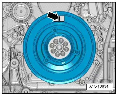
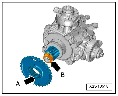
–  Insert high-pressure pump into chain sprocket.
l  The dual toothing -arrow A- on the chain sprocket must align with the groove -arrow B- in the adapter on the high-pressure pump shaft.
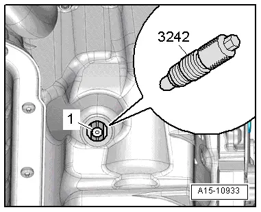
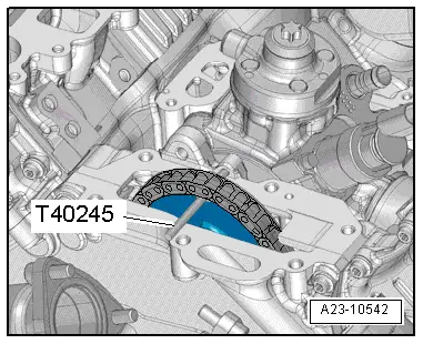
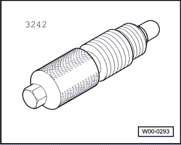
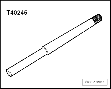
–  Remove locking pin -3242- and locking pin -T40245-.
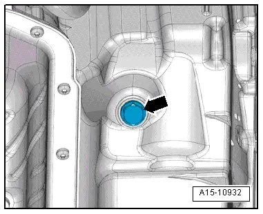
–  Tighten plug for „TDC“ drilling in sump (top section) → Rep. gr.17.
–  Install high-pressure pipes → Chapter.
–  Install coolant shut-off valve → Rep. gr.19.
–  Install engine oil cooler → Rep. gr.17.
–  Install turbocharger → Rep. gr.21.
–  Install intake manifold → Chapter.
–  Install rear noise insulation → Rep. gr.66.
  Caution
Running when dry causes irreparable damage to high-pressure pump.
After installing the high-pressure pump, the pump must first be filled with fuel before the engine is started for the first time → Chapter.
  A23-10518

Engine control unit > < Injection system