A5
| Exploded view of track control link, swivel joint, guide link, vehicle level sender |
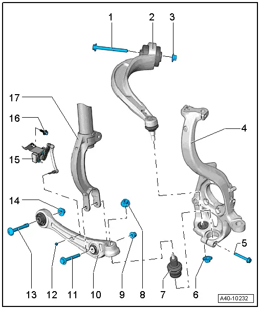
| 1 - | Bolt |
| q | Always renew if removed |
| 2 - | Guide link |
| q | Removing and installing → Chapter |
| q | Different versions (with conventional or hydraulic bonded rubber bush); for correct version, refer to → Electronic parts catalogue |
| q | Mixed installation is not permissible |
| q | Renewing conventional bonded rubber bush (65 mm Ø) for guide link → Chapter |
| q | Renewing hydraulic bonded rubber bush (75 mm Ø) for guide link → Chapter |
| 3 - | Nut |
| q | 70 Nm +180° |
| q | Always renew if removed |
| q | Vehicle must be in unladen position when tightening → Chapter |
| 4 - | Wheel bearing housing |
| 5 - | Bolt |
| q | 40 Nm |
| q | Always renew if removed |
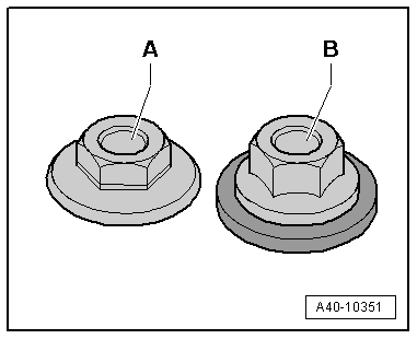
| 6 - | Nut |
| q | Always renew if removed |
| q | Different versions; for correct version, refer to → Electronic parts catalogue |
| q | Note different nut versions and tightening torques → Anchor |
| q | After detaching guide link from wheel bearing housing, remove residual adhesive from thread of joint pin. |
| 7 - | Swivel joint |
| q | Removing and installing → Chapter |
| q | Different versions; for correct version, refer to → Electronic parts catalogue |
 Note
Note| t | Note installation position → Anchor. |
| t | Insert swivel joint all the way onto contact surface on wheel bearing housing. |
| 8 - | Nut |
| q | Always renew if removed |
| q | Different versions; for correct version, refer to → Electronic parts catalogue |
| q | Note different nut versions and tightening torques → Anchor |
| q | After detaching swivel joint from wheel bearing housing, remove residual adhesive from thread of joint pin. |
| 9 - | Nut |
| q | 90 Nm +90° |
| q | Always renew if removed |
| q | Vehicle must be in unladen position when tightening → Chapter |
| 10 - | Track control link |
| q | Removing and installing → Chapter |
| q | Different versions; for correct version, refer to → Electronic parts catalogue |
| q | Renewing bush for track control link → Chapter |
| 11 - | Bolt |
| q | Always renew if removed |
| 12 - | Nut |
| q | 9 Nm |
| 13 - | Bolt |
| q | Always renew if removed |
| 14 - | Nut |
| q | 70 Nm +180° |
| q | Always renew if removed |
| q | Vehicle must be in unladen position when tightening → Chapter |
| 15 - | Front left vehicle level sender -G78-; front right vehicle level sender -G289- |
| q | Always install senders of the same version |
| q | Remove/install and renew only as a complete assembly → Chapter |
| q | Lever of sender must face towards rear |
| q | Check basic adjustment of headlights if sender mountings are loosened → Rep. gr.94 |
| q | If, on vehicles with electronic damping control, the vehicle level sender has been removed and refitted or the linkage detached, the reference position must be re-adapted → Chapter → Vehicle diagnostic tester. |
| q | If the reference position has been re-adapted on vehicles with lane departure warning, the lane departure warning control unit -J759- must be recalibrated → Chapter. |
| 16 - | Bolt |
| q | 20 Nm |
| 17 - | Shock absorber fork |