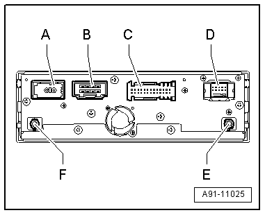
| Navigation system with CD drive control unit -J401- |
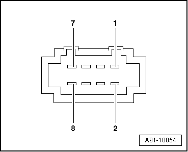
| B - | Multi-pin connector, 8-pin |
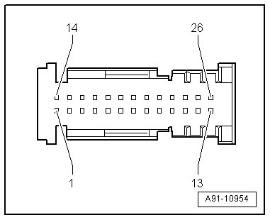
| C - | Multi-pin connector, 26-pin (T26) to chip card reader control unit -J676- / telephone transmitter and receiver unit -R36- |
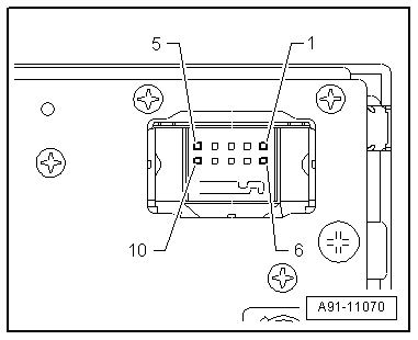
| D - | Multi-pin connector, 10-pin (LVDS wire) to control unit for front display and information control panel -J523- |
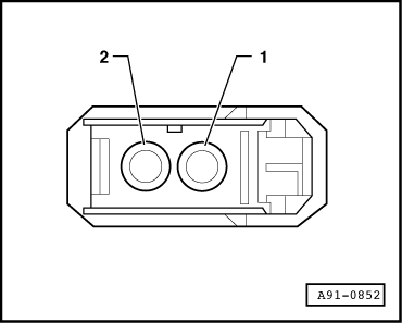
| E - | GPS connection from radio, telephone and navigation system aerial -R52- |
| F - | VICS connection from aerial amplifier 2 -R111- |

Note | Contacts which are not listed are not used. |
|
|
|