
Century V6-3100 3.1L VIN M SFI (1998)
Brake Master Cylinder: Description and Operation
MASTER CYLINDER
IMPORTANT:
^
Replace all of the components that are included in the repair kits used to service this master cylinder.
^
Lubricate the rubber parts with clean brake fluid in order to ease assembly.
^
Do not use lubricated compressed air on the brake parts. This action may cause damage to the rubber components.
^
If you remove or disconnect any hydraulic part, you may have to bleed all or part of the brake system.
^
The specified torque values are for dry, non-lubricated fasteners.
^
Perform the service operations on a clean bench that is free from all mineral oil materials.
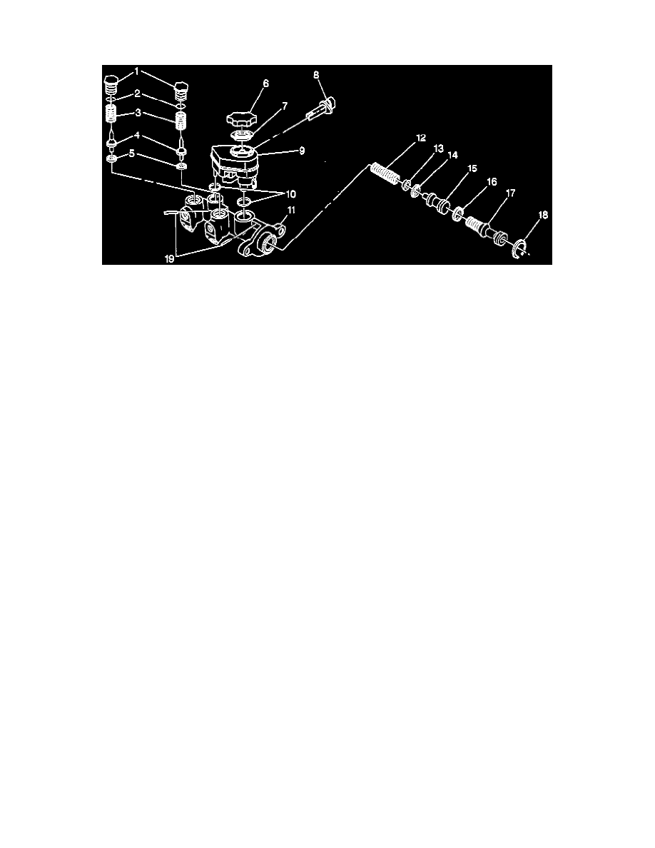
This master cylinder is a composite design with a plastic reservoir and an aluminum body. The master cylinder is used in a diagonally split system. In
this system, one front and one diagonally rear brake is served by the primary piston (17), and the opposite front and rear brakes are served by the
secondary piston (15).
The master cylinder incorporates the functions of a standard dual master cylinder. The master cylinder also has a fluid level sensor (8) and integral
proportioning. The proportioning valves are designed to provide better front-to-rear braking balance with a heavy brake application.
PROPORTIONING VALVES
IMPORTANT: Do not wash the proportioning valve in any cleaning solution. The internal components are prelubricated with a special grease.
The proportioning valves are located in the master cylinder. The proportioner valves thread into the master cylinder. The proportioning valves
proportion the brake fluid to each caliper or wheel cylinder after a predetermined amount of pressure is reached. The proportioner valves limit outlet
pressure to the rear brakes after the brakes meet a predetermined inlet pressure. The proportioner valves limit pressure when less apply force is needed
in order to obtain optimum breaking. The proportional valves prevent rear wheel lock-up on vehicles that do not have heavy rear wheel loads.
FLUID LEVEL SENSOR
The compact master cylinders are equipped with a fluid level sensor. The sensor switch is located in the inboard side of the reservoir. The sensor
activates the BRAKE warning lamp if the fluid level is low. The BRAKE warning lamp turns off when the fluid level is corrected. For electrical
details on the BRAKE warning system, refer to Brake Warning System in Electrical Diagnosis.
Anti-Lock Brake System
The anti-lock brake system uses a amber ANTI-LOCK lamp indicator lamp.
The lamp is located in the instrument panel cluster. Ensure that the lamp exhibits the following conditions under normal conditions:
^
he amber ANTI-LOCK lamp turns ON when the ignition is turned to the RUN position, prior to starting the engine.
^
The amber ANTI-LOCK lamp comes ON as the engine is cranked.
^
Ensure that the lamp is OFF when the engine starts. The operation of the warning lamp is an important part of the anti-lock brake system
diagnosis. If the warning lamp turns ON when you are driving the vehicle, this indicates a malfunction. For additional information regarding
warning lamp operation for the anti-lock brake system, refer to Antilock Brake System or Electrical Diagnosis.
SUBSTANDARD OR CONTAMINATED BRAKE FLUID
CAUTION: Brake fluid may irritate eyes and skin. In case of contact, take the following actions:
^
Eye contact-rinse thoroughly with water.
^
Skin contact-wash with soap and water.
^
If ingested consult a physician immediately.