
LeSabre V6-181 3.0L (1986)
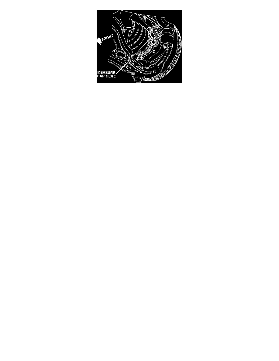
Fig. 1 Wheel Speed Sensor Air Gap
1.
Follow steps 2 and 4 of the sensor removal procedure.
2.
Follow steps 1 to 3 of the sensor installation procedure.
3.
Follow the appropriate procedure:
Type 1 Sensor:
A.
Loosen the adjustment screw so that the sensor slides freely on its sleeve.
B.
Place a non-ferrous feeler gauge between the toothed ring and the sensor face:
^ Use a 0.7mm (0.028-inch) thickness for 1986 A/C-body.
^ Use a l.O mm (0.040-inch) thickness for 1987 to 1988 C/H-body.
C.
Lightly push the sensor against the feeler gauge. Tighten the adjustment screw to 2.5 N-m (22 lb. in.) torque.
D.
Remove the feeler gauge.
Type 2 Sensor:
A.
Loosen the mounting bracket bolts.
B.
Place a non-ferrous feeler gauge between the toothed ring and the sensor face:
^ Use a 0.5 mm (0.020-inch) thickness for 1988 and 1989 E-Body.
C.
Lightly push the sensor/bracket against the feeler gauge. Tighten the mounting bolts to 12 N-m (9 lb. ft.) torque.
D.
Remove the feeler gauge.
Type 3 Sensor:
A.
Loosen the mounting bracket bolt.
B.
Place a non-ferrous feeler gauge between the toothed ring and the sensor face:
^ Use a 0.7mm (0.028-inch) thickness for 1986 C-body and 1986 to 1989 A-body.
C.
Lightly push the sensor against the feeler gauge. Tighten the mounting bolt to 2.5 N-m (22 lb. in.) torque.
4.
Follow steps 6 and 8 of the sensor installation procedure.
NOTE: TYPE 4 SENSORS ARE NOT ADJUSTABLE