
LeSabre V6-181 3.0L (1986)
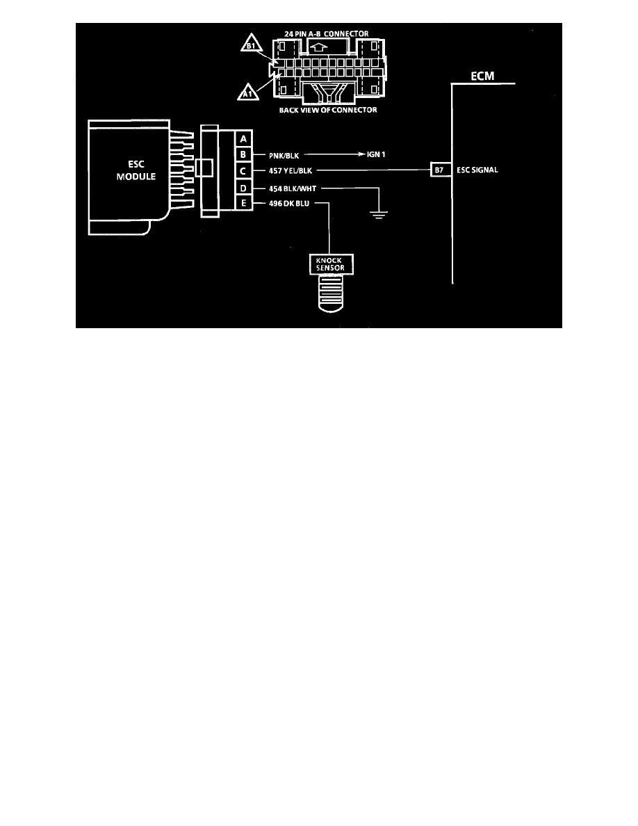
Wiring Diagram for Chart C-5 - Electronic Spark Control (ESC) System Check
CHART C-5 - ELECTRONIC SPARK CONTROL (ESC) SYSTEM CHECK (ENGINE KNOCK, POOR PERFORMANCE OR POOR ECONOMY)
Circuit Description:
Electronic spark control is accomplished with a module that sends a voltage signal to the ECM. As the knock sensor detects engine knock, the voltage
from the ESC module to the ECM is shut "OFF" and this signals the ECM to retard timing.
Test Description:
Numbers below refer to circled numbers on the diagnostic chart.
1.
Test ESC to see if it can detect a knock and retard the timing.
2.
By disconnecting the ESC module, the ECM sees low voltage at terminal "B7" and should retard timing. After approximately 4 seconds, "Service
Engine Soon" light will come "ON" and Code 43 will be stored.
3.
Checks for proper voltage output (measured on AC scale) of knock sensor. Low or no voltage would indicate an open circuit to terminal "E" or
faulty sensor.
4.
Checks to see if constant retard's due to a faulty knock sensor or module, or if a false voltage signal is being transmitted on the wire from the knock
sensor by induction from an adjacent wire, such as a spark plug wire, ignition wire, etc. Reroute wires as necessary.