
LeSabre V6-181 3.0L (1986)
Voltage Regulator: Testing and Inspection
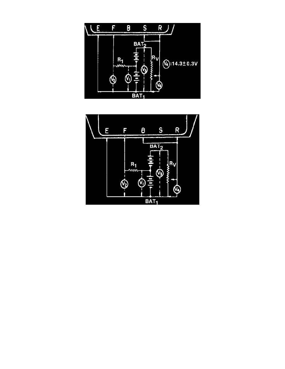
Fig. 1 IC regulator preliminary test connections
Fig. 2 IC regulator final test connections
To perform regulator tests, the following measuring instruments will be needed: resistor (10 ohms, 3 watts) R1, variable resistor (0---300 ohms, 3
watts) RV, battery (12 volts, 2 pieces). BAT1, BAT2, DC voltmeter (0---30 volts).
1.
Connect instruments as shown in Fig. 1.
2.
Measure voltage at BAT1 (V1). Voltmeter reading should be 10---13 volts.
3.
Measure voltage between terminals F and E (V2). Voltmeter reading should be approximately 2 volts.
4.
Measure voltage between BAT1 and BAT2 (V3) with terminal S disconnected. Voltmeter reading should be 20---26 volts.
5.
Measure voltage between terminals E and F while varying resistance gradually with variable resistor. Voltage should increase from 2 volts to
10---13 volts without any interruption. If voltage increase is interrupted, replace regulator.
6.
Measure voltage between intermediate tap on variable resistor and terminal E (V4) without actuating variable resistor. Voltmeter should read
14.0---14.6 volts, or regulator must be replaced.
7.
Connect instruments as shown in Fig. 2.
8.
Measure voltage between terminals B and E while gradually increasing voltage with variable resistor. Voltage should increase from approximately
2 volts to 10---13 volts. If voltage does not vary, replace regulator.
9.
Check voltage between intermediate tap of variable resistor and terminal E without actuating variable resistor. Voltmeter should read 14.5---16.6
volts, or regulator must be replaced.