
Rainier AWD L6-4.2L (2007)
Step 25 - Step 29
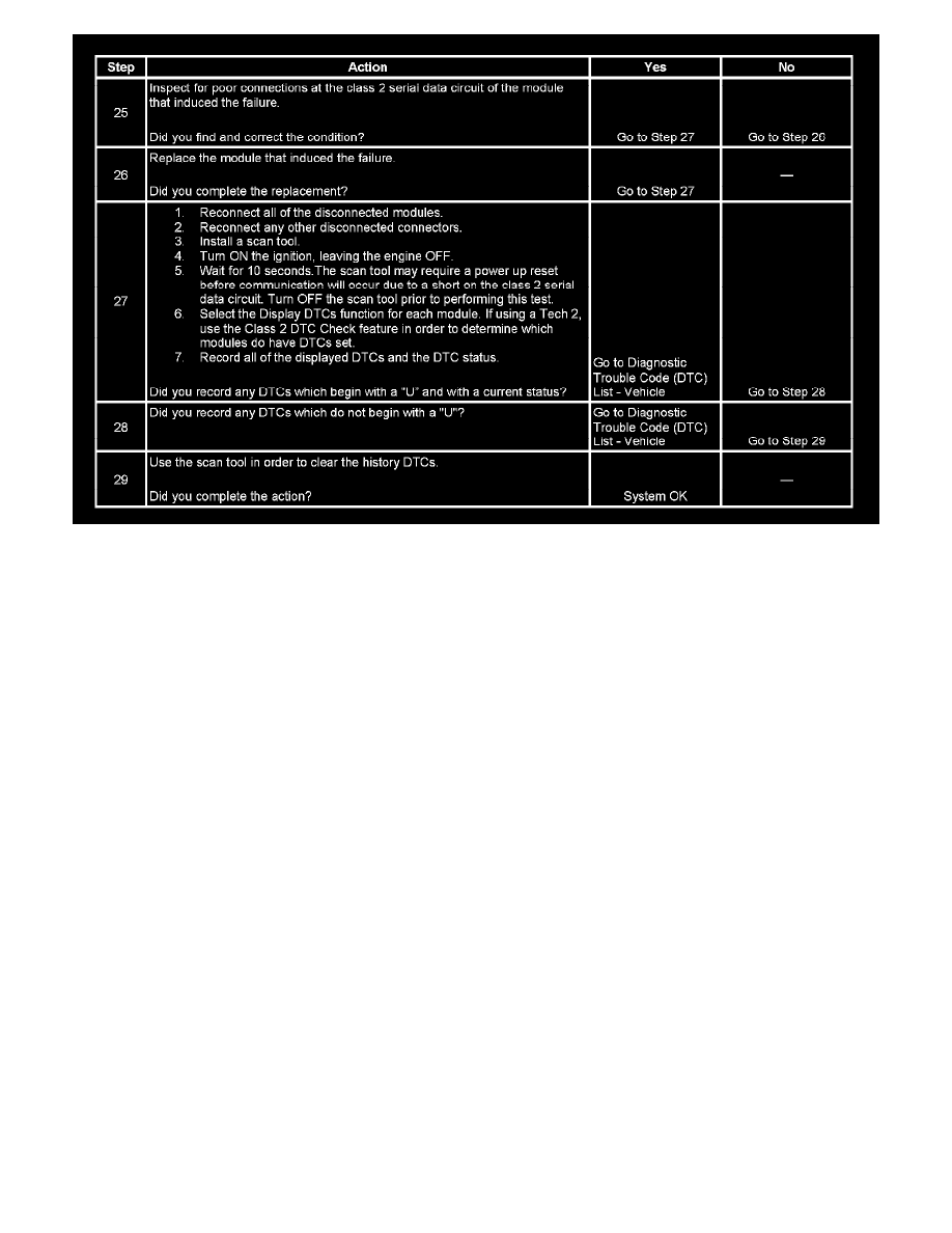
The numbers below refer to the step numbers on the diagnostic table.
2. A partial malfunction in the class 2 serial data circuit uses a different procedure from a total malfunction of the class 2 serial data circuit. The
following modules communicate on class 2 serial data bus:
-
The body control module (BCM)
-
The communication interface module (OnStar(R)), w/UE1
-
The digital radio receiver (DRR), w/U2K
-
The driver door module (DDM)
-
The driver seat module (DSM), w/AAB
-
The DVD player
-
The electronic brake control module (EBCM)
-
The HVAC control module
-
The HVAC control module - rear auxiliary
-
The inflatable restraint sensing and diagnostic module (SDM)
-
The instrument panel cluster (IPC)
-
The liftgate control module (LGM)
-
The passenger door module (PDM)
-
The powertrain control module (PCM)
-
The radio
-
The transfer case shift control module (TCSCM), w/4WD
3. The following DTCs may be retrieved with a history status, but are not the cause of the present condition.
-
U1300
-
U1301
-
U1305
6. A state of health (SOH) DTC with a history status may be present along with a U1000 code having a current status. This indicates that the
malfunction occurred when the ignition was ON.
7. Data link connector terminals 2 and 5 provide the connection to the class 2 serial data circuit and the signal ground circuit respectively.
10. A poor connection at DLC terminal of the splice pack SP205 would cause this condition but will not set a DTC.
11. An open in the class 2 serial data circuit between the DLC and splice pack SP205 will prevent the scan tool from communicating with any module.
This condition will not set a DTC.
12. The class 2 serial data circuit is shorted to voltage or ground. The condition may be due to the wiring or due to a malfunction in one of the
modules. When testing the wire for a short, make sure there is not a module connected to the wire being tested. This test isolates the BCM and the
PCM class 2 serial data circuits.
13. This test isolates the BCM class 2 serial data circuits.
16. The BCM detects that the ignition is ON and sends the appropriate power mode message to the other modules. Therefore, the BCM must remain
connected to the DLC for any other module to communicate with the scan tool. This test isolates the splice pack SP306 serial data circuits.