
Regal V6-3100 3.1L VIN M SFI (1996)
Turn Signal Switch: Service and Repair
Fixed Columns
Fig. 59 Disconnecting Switch Wires
TURN SIGNAL CANCEL CAM, PIVOT & PULSE SWITCH & TURN SIGNAL SWITCH
DISASSEMBLE
1. Remove nut retainer, jam nut and steering wheel.
2. Remove turn signal cancel cam assembly, hazard knob screw and hazard warning knob.
3. Position turn signal switch so that signal switch screws and housing cover screw can be removed through openings in switch.
4. Remove housing cover screw and column housing cover.
5. Disconnect wiring protector from opening in instrument panel bracket on jacket and bowl assembly and separate from wires.
6. Disconnect pivot and pulse switch connector from ignition and dimmer switch.
7. Remove pivot switch screw and pivot and pulse switch assembly.
8. Remove turn signal switch screws and disconnect turn signal switch connector from ignition and dimmer switch assembly connector.
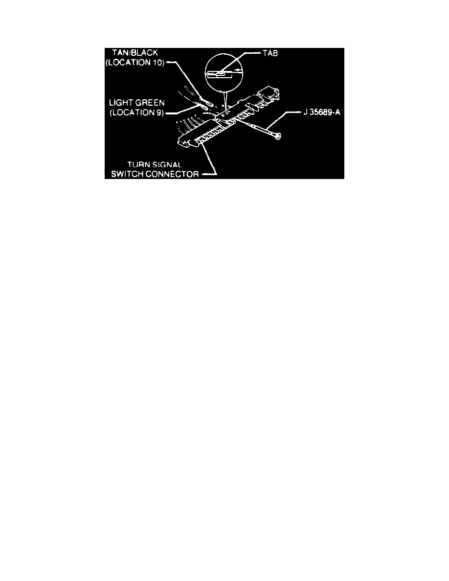
9. Remove 17-way lock from turn signal connector and disconnect wires on alarm or buzzer assembly from turn signal connector with terminal
removal tool No. J-35689-A, or equivalent, Fig. 59. Wrap wire ends with tape to protect during removal and installation.
10. Remove turn signal switch assembly from column.
ASSEMBLE
1. Install turn signal switch assembly. Torque screws to 35 inch lbs.
2. Connect wires from alarm or buzzer assembly to turn signal switch connector.
3. Install 17-way secondary lock to turn signal connector and snap in place.
4. Connect turn signal switch connector to ignition and dimmer switch connector and snap in place.
5. Install pivot and pulse switch assembly. Torque screw to 18 inch lbs.
6. Connect pivot switch connector to ignition and dimmer switch connector and snap in place.
7. Install wiring protector as follows:
a. Wrap protector around all wires passing through instrument panel bracket opening.
b. Close protector so that interlocking grooves engage and slide protector into instrument panel bracket opening on jacket and bowl assembly and
snap in place.
8. Install column housing cover. Torque screw to 35 inch lbs.
9. Install hazard warning knob. Torque screw to 9 inch lbs.
10. Lubricate bottom side of cancel cam with lithium grease and install turn signal cancel cam assembly.
11. Install steering wheel and jam nut. Torque jam nut to 30 inch lbs. and secure with nut retainer.