
Rendezvous AWD V6-3.5L VIN L (2006)
Axle Shaft: Service and Repair
Front
Wheel Drive Shaft Replacement - Front
^
Tools Required
-
J 2619-O1 Slide Hammer
-
J 29794 Axle Shaft Remover Extension
-
J 33008-A Axle Shaft Puller
-
J 42129 Wheel Hub Remover
Removal Procedure
Important: Prevent the seals (boots) from contacting the other components in order to prevent damage to the seals (boots).
1. Raise and support the vehicle. Refer to Vehicle Lifting.
2. Remove the tire and wheel assembly.
3. Remove the engine splash shield.
4. Remove the stabilizer shaft link.
5. Disconnect the electrical connector from the wheel speed sensor.
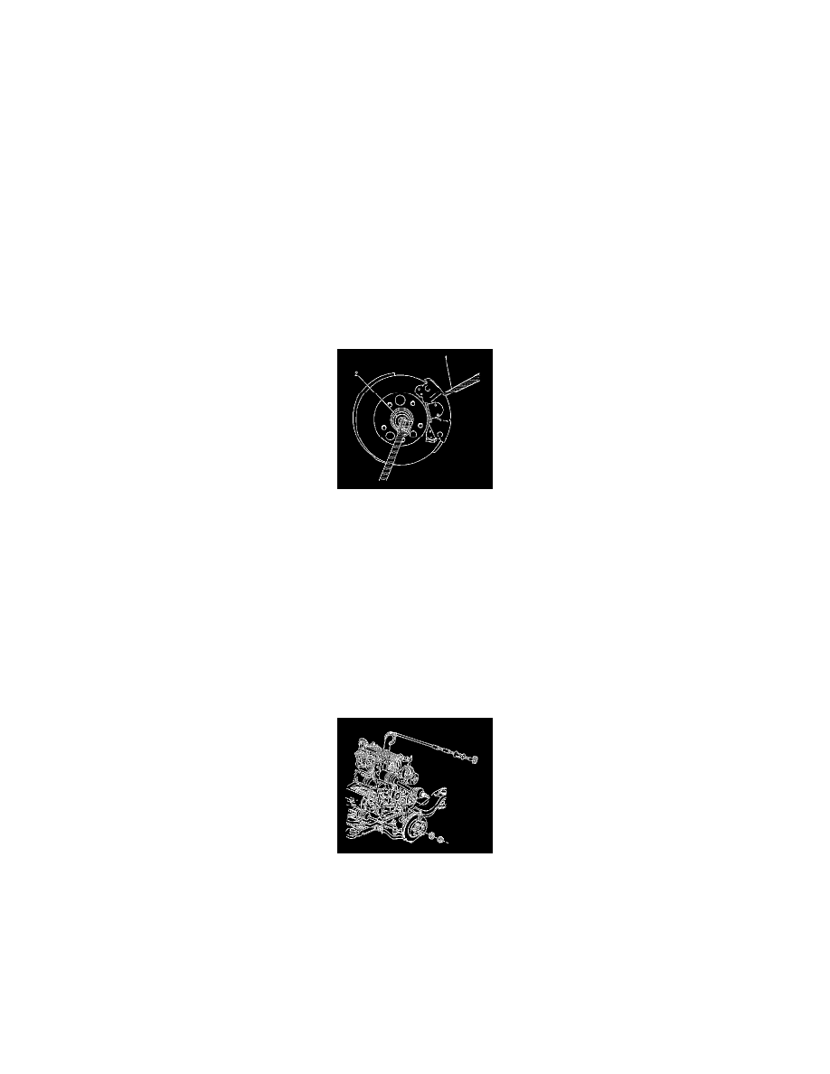
6. Important: Note the relationship between the halves of the 2-piece ramped washer. The ramped sides must face each other when installing the
washer.
Remove the front wheel drive shaft nut (2) and the ramped, 2-piece washer. Insert a drift or a flat-bladed tool (1) through the caliper and into the
brake rotor to prevent the rotor from turning.Discard the wheel drive shaft nut.
7. Disconnect the outer tie rod end from the steering knuckle; do NOT loosen the tie rod end jam nut.
8. Disconnect the lower ball joint from the steering knuckle.
9. Install the J 42129 onto the wheel hub and bearing and secure with wheel nuts.
10. Caution: Do not attempt to move vehicle with drive axle(s) removed from wheel bearing. Wheel(s) could fall off, dropping vehicle to the ground
and causing personal injury or damage to the vehicle.
Using the J 42129 , disengage the wheel drive shaft from the wheel hub and bearing and support the wheel drive shaft.
11. Assemble the J 2619-O1 , the J 29794 , and the J 33008-A.
12. Using the J 2619-O1 , the J 29794 , and the J 33008-A , disengage the wheel drive shaft from the transaxle.
13. Remove the wheel drive shaft from the vehicle.
14. Remove and discard the wheel drive shaft retaining ring.
^
On the right wheel drive shaft, the retaining ring is on the splined shaft of the inner tripot housing.
^
On the left wheel drive shaft , the retaining ring is on the splined transmission output shaft.
Installation Procedure