
Riviera V6-3.8L SC VIN 1 (1995)
Revised Crankshaft Balancer Design
Has a round hole drilled in the face of the crankshaft balancer. Figure 1 View A. This hole does not aid in the alignment of J 38197-2, like the dimple on
the previous designed crankshaft balancer. The hole is used to identify the crankshaft key location in relation to the slot in the crankshaft balancer. The
special tool (J 38197) has been revised to reflect the design changes and the new tool is J 38197-MOD. (If you already have J 38197 it is necessary to
only order the J 38197-MOD). The revised crankshaft balancer requires the use of three bolts (J 38197-4), these bolts are 1/4 inch longer than the
previous design. J 38197-4 are silver in color while the previous tool uses black bolts.
J 38197-4 should not be used to service the previous design crankshaft balancer as damage to the balancer may occur by using the longer bolts.
The revised crankshaft balancer may have burrs on the slotted access holes that do not allow the proper alignment of J 38197. If burrs are present,
remove them by using one of the following methods:
^
File access hole using rat-tail file in proper location.
^
Drill access hole using drill in proper location.
^
Bend access hole using screw driver in proper location.
Revised Crankshaft Balancer Service Procedure Figures 1, 2 and 3
Tools Required:
J 36660 Torque Angle Meter
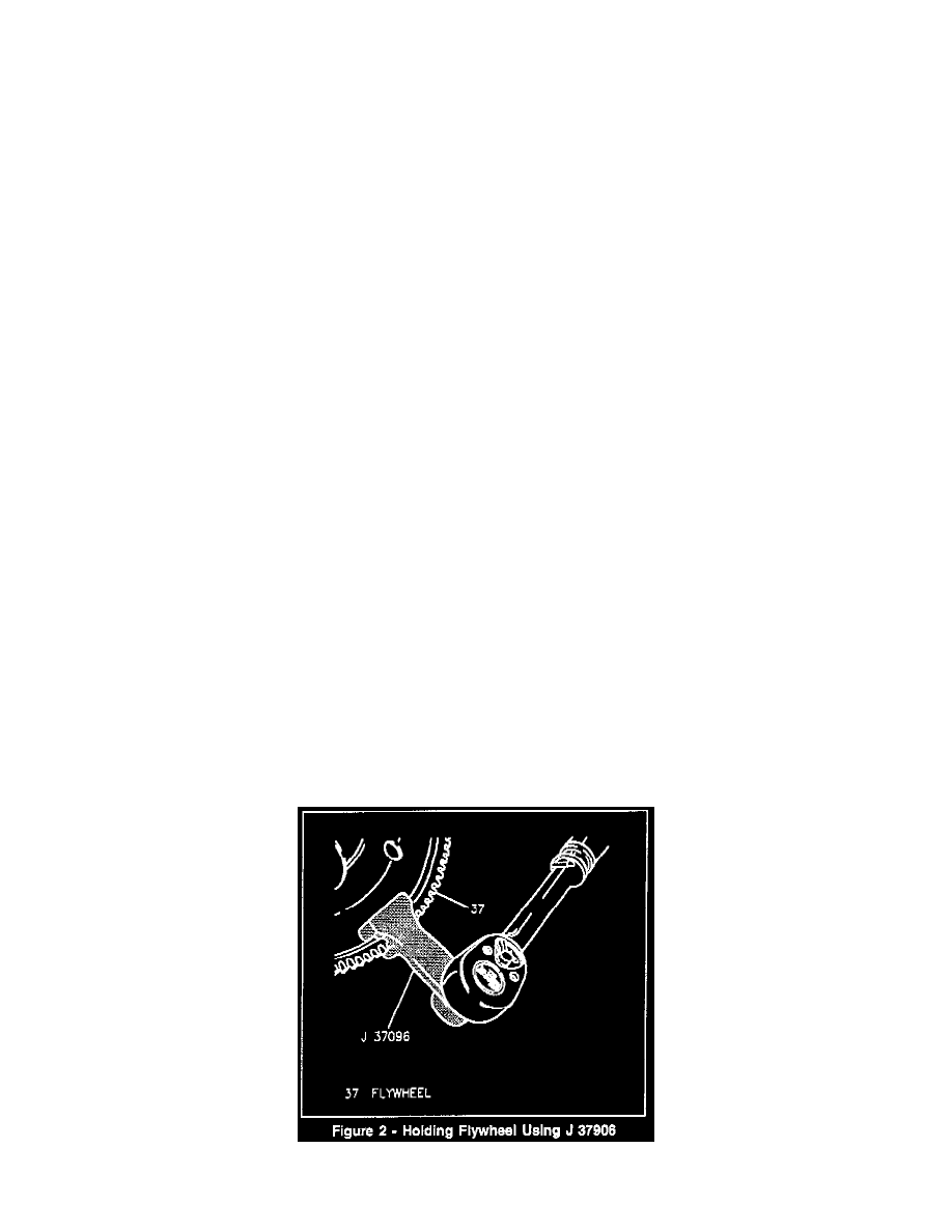
J 37096 Flywheel Holding Tool
J 38197-A and J 38197-MOD Crankshaft Balancer Puller
J 38197-A Includes:
J 38197-1 Pilot Screw
J 38197-2 Puller Plate
J 38197-3 Puller Screws (Black)
J 38197-4 Puller Screws (Silver)
J 38197-MOD includes:
J 38197-4 Puller Screws (Silver)
Remove or Disconnect
1.
Hold flywheel using J 37096 (Figure 2).