
Riviera V6-3.8L SC VIN 1 (1995)
Data Link Connector: Description and Operation
Circuit Operation
Data Link Connectors (DLC)
DESCRIPTION
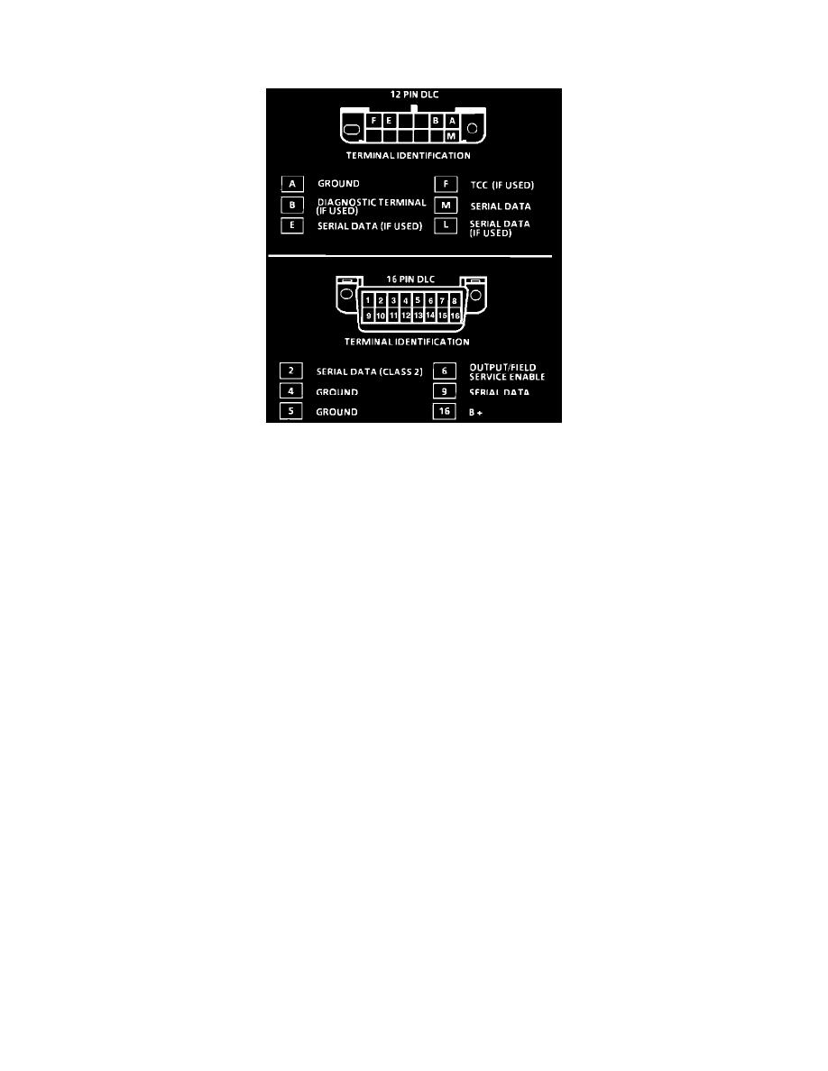
The provision for communicating is the Data Link Connector (DLC). It is usually located under the instrument panel and is sometimes covered by
a plastic cover labeled "DIAGNOSTIC CONNECTOR." It is used in the assembly plant to receive information in checking that the engine is
operating properly before it leaves the plant. The connector can also be used by the service technician to identify stored trouble codes and to read
Powertrain Control Module (PCM) data using a hand held scan tool.
OPERATION
The system can communicate a variety of information through the DLC. This data is transmitted at a high frequency which requires a Tech 1
Diagnostic Computer (or equivalent scan tool) for interpretation. There are several scan tools available for reading this information.
With an understanding of the data which the tool displays, and knowledge of the circuits involved, the tool can be very useful in obtaining
information which would be more difficult or impossible to obtain with other equipment.
Tech 1 and scan tools do not make the use of diagnostic trouble code charts unnecessary, nor can they indicate exactly where a problem is in a
particular circuit. These charts Incorporate diagnosis procedures using a Tech 1 tool where possible and most charts require the use of a Tech 1
when it is applicable.
NOTE: Tech 1 tool that displays faulty data should not be used and the problem should be reported to the manufacturer. The use of a faulty scan
tool can result in misdiagnosis and unnecessary parts replacement.