
Skylark L4-138 2.3L DOHC VIN D MFI (1988)
Remove or Disconnect
1. Negative battery cable
2. Coolant fan shroud (including vacuum hose and electrical connector from MAP sensor)
3. Throttle body to air cleaner duct
4. Throttle cable bracket
5. Power brake vacuum hose (including retaining bracket to power steering bracket) and position aside
6. Throttle body from intake manifold with electrical harness, coolant hoses, vacuum hoses and throttle cable attached. Position aside.
7. Oil/air separator (crankcase ventilation system) (2) bolts and (4) hoses. Leave the hoses attached to the separator, disconnect from the oil fill, chain
housing, and the intake manifold. Remove as an assembly.
8. Oil fill cap and oil level indicator assembly
9. Pull oil tube fill upward to unseat from block
10. Injector harness connector
11. Remove fill tube out top, rotating as necessary to gain clearance for oil/air separator nipple between intake tubes and fuel rail electrical harness.
12. Intake manifold support bracket (2) bolts (1) nut
13. Manifold retaining nuts and bolts
14. Remove manifold and gasket
^
Hole closest to chain housing is slotted for additional clearance
Install or Connect
1. Manifold and gasket
2. Following tightening sequence, tighten bolts/nuts to specification
3. Install intake manifold brace and retainers hand tight. Then tighten to specifications in the following sequence:
a.
Nut to stud bolt
b.
Bolt to intake manifold
c.
Bolt to cylinder block
4. Lubricate a new oil fill tube "0" ring seal with engine oil and install tube down between numbers 1 and 2 intake tubes. Rotate as necessary to gain
clearance for oil/air separator nipple on fill tube
5. Locate the oil fill tube in its cylinder block opening. Align the fill tube so it is approximately in its installed position. Place the palm of your hand
over the oil fill opening and press straight down to seat fill tube and "0" ring into cylinder block.
6. Oil/air separator assembly (it may be necessary to lubricate the hoses for ease of assembly)
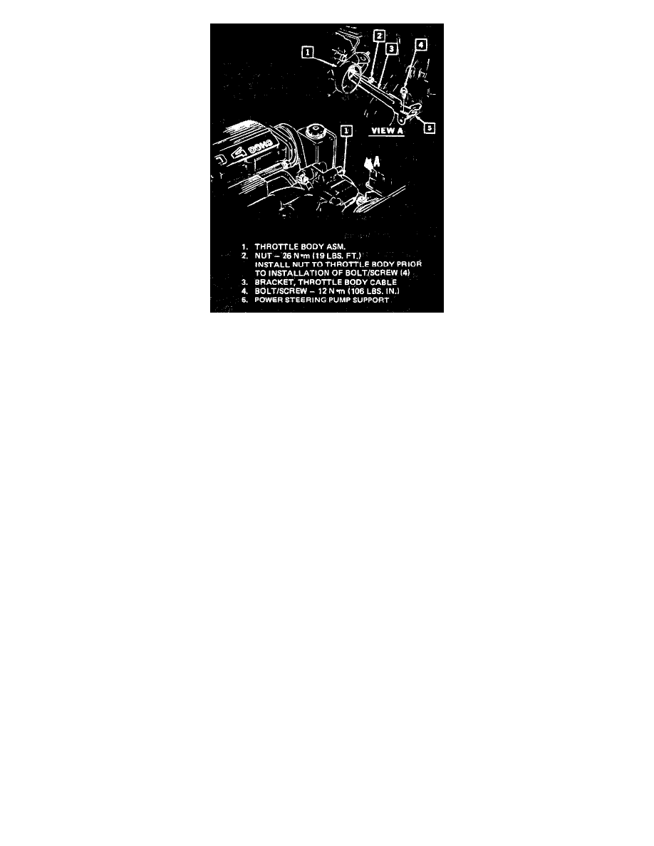
7. Throttle body to intake manifold using a new gasket.
8. Powerbrake vacuum hose to throttle body and secure pipe to power steering bracket
9. Throttle cable bracket
^
Install nut (2) to throttle body prior to installation of bolt/screw (4).
10. Coolant fan shroud (including vacuum line to MAP sensor)
11. Electrical connector to MAP sensor
12. Negative battery cable
Inspect
^
For leaks