
Skylark L4-144 2.4L DOHC VIN T SFI (1997)
Information Bus: Initial Inspection and Diagnostic Overview
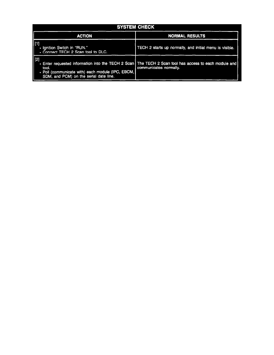
System Check
Troubleshooting Hints
PERFORM BEFORE BEGINNING SYSTEM DIAGNOSIS
CAUTION: The SIR driver deployment loop (CKT 347 and 348) passes through connector C200. You must take special precautions before
servicing connector C200. Disable the SIR system before you disconnect, probe, or service connector C200. Refer to "Disabling the SIR
System" in Air Bags and Seat Belts. Failure to follow the correct procedure could cause air bag deployment, personal injury, or unnecessary
SIR system repairs. See: Restraint Systems
SERIAL DATA LINE (UART)
1. If all components are not accessible with a scan tool, check for an open in CKT 800 between DLC terminal "9" and 5277 or short to B+ or ground.
2. If a single component is not accessible with a scan tool, check for an open in CKT 800. If the wire is OK, refer to Antilock Brake System for
ABS diagnosis, and to Air Bags and Seat Belts for Supplemental Air Restraint diagnosis, and Instrument Panel for Instrument Panel Cluster
diagnosis.
See: Brakes and Traction Control/Antilock Brakes / Traction Control Systems
See: Restraint Systems
See: Instrument Panel, Gauges and Warning Indicators
SERIAL DATA LINE (CLASS 2)
1. If Powertrain Control Module (PCM) is not accessible with a scan tool, check for an open in CKT 1807.
^
Refer to System Diagnosis.
^
Check for a broken (or partially broken) wire inside of the insulation which could cause system malfunction but prove "GOOD" in a
continuity/voltage check (refer to Troubleshooting Procedures).
^
Check for proper installation of aftermarket electronic equipment which may affect the integrity of other systems (refer to Troubleshooting
Procedures). See: Diagrams/Diagnostic Aids