
Skylark V6-3100 3.1L VIN M SFI (1996)
36.
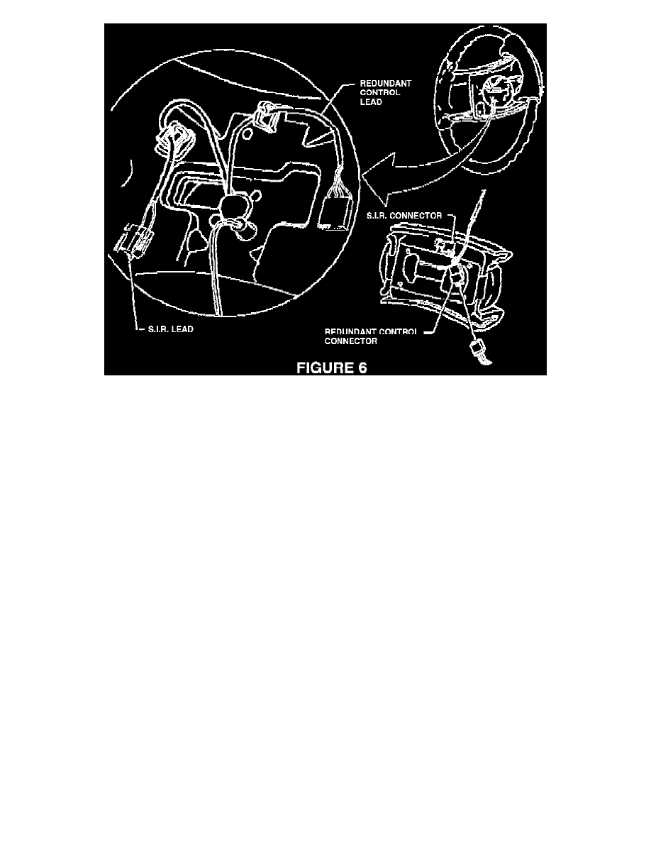
Position S.I.R. and R.R.C. up leads into steering wheel routing clips as shown in fig. 6.
IMPORTANT:
THESE LEADS MUST BE ROUTED CORRECTLY. IMPROPER ROUTING OF THESE LEADS CAN RESULT IN PINCHED WIRES AND
SHORTED CIRCUITS.
37.
Position S.I.R. module onto steering wheel.
38.
Unlock steering column and rotate as required to install two S.I.R. module attaching screws (10 mm hex) from back of steering wheel. Tighten
screws to 9 N.m (6.6 lbs. ft.).
39.
Re-connect courtesy lamp harness to courtesy lamp on sound insulator. Replace S.I.R. harness edge clip to edge of panel. Re-install LH sound
insulator (one nut, two twist retainers),
IMPORTANT:
MAKE SURE THAT ALL WIRING HARNESSES ARE PROPERLY ROUTED AND NOT PINCHED AT ANY LOCATION.
40.
Re-install upper steering column bottom cover with three screws. Tighten to 4 N.m (2.9 Lbs. ft.) following sequence shown in figure 3.
41.
Re-install upper steering column top cover (snap-in). See figure 3.
42.
On column-shift vehicles, re-install shift lever boot using the following procedure. See figure 2.
a.
Rotate ignition key to "RUN" position.
b.
Shift transaxle into "NEUTRAL" position.
c.
Slide column shift lever boot down on shaft of column shift lever until the boot contacts the steering column cover.
d.
At the 3 o'clock position, move boot inward and then forward.
e.
At the 6 o'clock position, move the boot downward.
f.
At the 9 o'clock position, push the boot inward to fully engage two attachment fingers.