
Skylark V6-3100 3.1L VIN M SFI (1996)
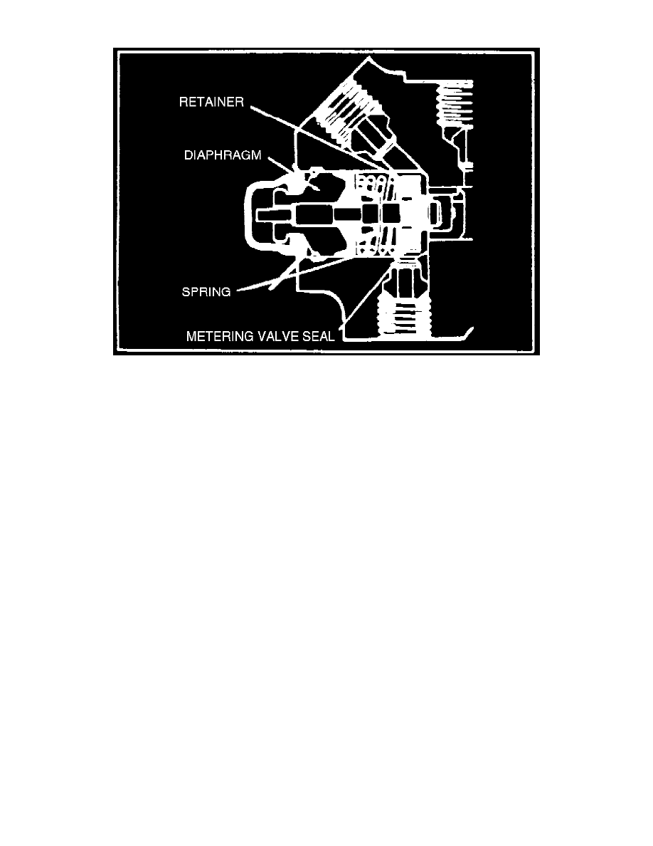
Fig. 6 Metering Valve. Initial Braking
Fig. 7 Metering Valve. Continued Braking
DESCRIPTION
When the brakes are not applied, the metering valve permits the brake fluid to flow through the valve, thus allowing the fluid to expand and contract
with temperature changes.
OPERATION
When the brakes are initially applied, the metering valve stem moves to the left, preventing fluid to flow through the valve to the front disc brakes.
This is accomplished by the smooth end of the metering valve stem contacting the metering valve seal lip at 4 to 30 psi, Fig. 6. The metering valve
spring holds the retainer against the seal until a predetermined pressure is produced at the valve inlet port which overcomes the spring pressure and
permits hydraulic pressure to actuate the front disc brakes, Fig. 7. The increased pressure into the valve is metered through the valve seal, to the front
disc brakes, producing an increased force on the diaphragm. The diaphragm then pulls the pin, in turn pulling the retainer and reduces the spring
pressure on the metering valve seal. Eventually, the pressure reaches a point at which the spring is pulled away by the diaphragm pin and retainer,
leaving the metering valve unrestricted, permitting full pressure to pass through the metering valve.
Failure Warning Switch