
Skylark V6-3100 3.1L VIN M SFI (1996)
Control Arm Bushing: Service and Repair
On-Vehicle Service
^
Tools Required:
-
J 21474-18 3/8in Nut
-
J 2147-19 3/8in Long Bolt and Bearing
-
J 29376-A Rear Control Arm Bushing Service Set
-
Or Equivalents
REMOVAL
Remove or disconnect the following:
1. Raise vehicle and suitably support.
2. Support vehicle with jackstands under axle.
3. Wheel and tire assemblies.
4. If removing right bushings, disconnect brake lines from body. If left bushings are being removed, disconnect brake line bracket from body, and
parking brake cable from hook guide on the body.
5. Nut, bolt, and washer from the control arm and underbody attachment, and rotate control arm downward. (Remove and install one control arm
bushing at a time.)
CAUTION: Do not suspend rear axle by brake hoses. Damage to hoses could result.
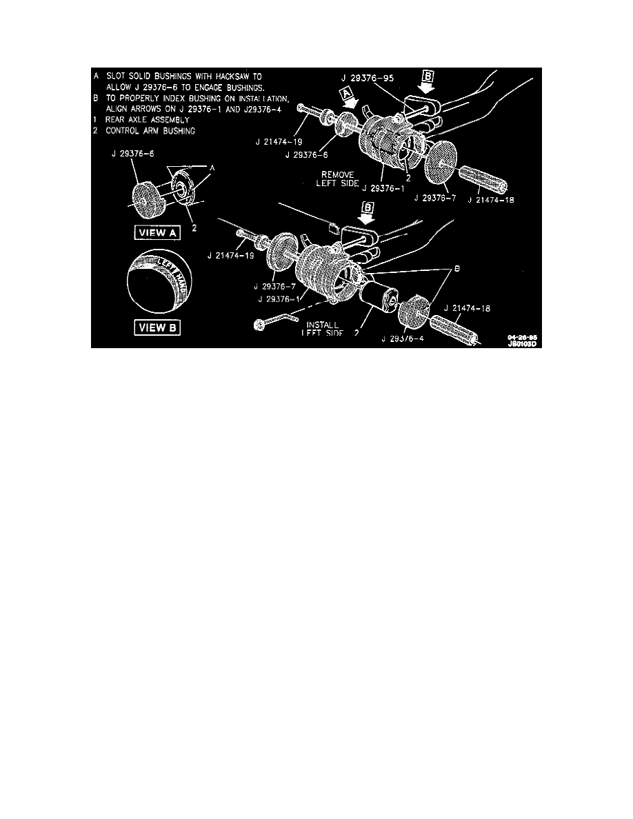
6. Bushing as follows:
A. Install J 29376-2 into slot in control arm, then position J-29376-1 over control arm end\bushing. Install J hooks through J-29376-1 and
J-29376-2 and tighten attaching nuts until tool is securely in place.
B. Install J 21474-19 bolt through plate J 29376-7 and install into J 29376-1 receiver.
C. Place J 29376-6A remover into position on bushing and install nut J 21474- 18 onto J 21474-19 bolt.
D. Bushing from control arm by turning bolt.
INSTALLATION
Install or connect the following:
1. Bushing as follows:
A. J 29376-1 receiver on control arm.
B. J 21474-19 bolt through plate J 29376-7 and install into J 29376-1 receiver.
C. Bushing on bolt and position into housing. Align bushing installer arrow with arrow on receiver for proper indexing of bushing. (A high
pressure lubricant such as J 23441A or equivalent may be necessary to aid in assembly.)
D. Nut J 21474-18 onto bolt J 21474-19.
E. Press bushing into control arm by turning bolt. When bushing is in proper position, the end flange will be flush against the face of the control
arm.
2. Align control arm and underbody attachment, and loosely install bolt, washer, and nut.