
Terraza FWD V6-3.5L VIN 8 (2005)
3. To assemble the connector, reverse the Terminal Removal Procedure.
Delphi Connectors (Micro .64)
DELPHI CONNECTORS (MICRO.64)
TOOLS REQUIRED
J-38125 Terminal Repair Kit
REMOVAL PROCEDURE
Follow the steps below in order to remove terminals from Micro 64 connectors.
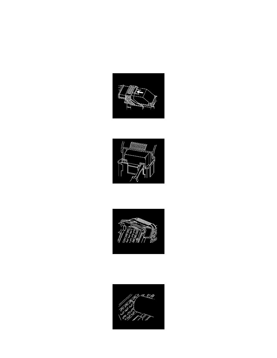
1. Locate the lever lock on the wire dress cover. While depressing the lock, pull the lever over and past the lock.
2. Disconnect the connector from the component.
3. Locate the dress cover locking tabs at the front of the connector. Using a small flat-blade tool push down on one of the locking tabs and pull the
cover up until the dress cover releases. Repeat this procedure for the other locking tab.
4. Once the front 2 locks are unlocked, lift the front of the dress cover and pull it forward.
5. Remove the TPA by inserting a small flat-blade tool into the small slot on the TPA and pushing down until the TPA releases. Gently pry the TPA
out of the connector.
IMPORTANT: Always use care when removing a terminal position assurance (TPA) in order to avoid damaging it.
6. Insert the J 38125-13A (GM P/N 12031876-1) tool into the round canal between the terminals cavities at the front of the connector. See the release
tool cross reference in the Reference Guide of the J-38125 to ensure that the correct release tool is used.