
Astro Van L AWD V6-262 4.3L VIN W CPI (1992)
REMOVE OR DISCONNECT (Figure 1, 5, 6, 7, and 8)
1.
Remove the front output flange nut (1), steel flat washer (2) and rubber sealing washer (3) from the front output shaft (4).
2.
Remove the front output flange (5) from the front output shaft (4)
3.
Remove the front cover bolts (9) from the rear case half (10). . The identification tag (40) is an aluminum tag attached under one of the
self-tapping case bolts. Every attempt should be made to keep the identification tag with the unit.
4.
Remove the case half dowel pins (42), quantity of 2, by using a mallet and punch.
5.
Remove the front cover (11) by prying on the tabs (1) provided on the case halves.
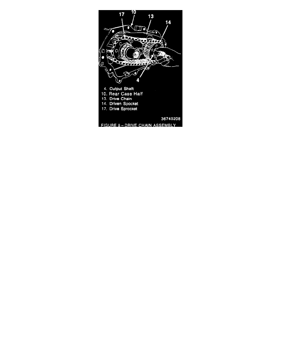
6.
Remove the drive chain (13) from the output shaft (4), driven sprocket (14) and the drive sprocket (17).
7.
Remove gasket material thoroughly from the both halves of the transfer case.
CLEANING AND INSPECTION
Clean:
Make sure the internal gears, sprockets and shafts are clean and free of foreign material.
Inspect:
1.
Inspect for excessive wear or damage, spalling, cracks, or corrosion on internal parts of the transfer case.
2.
Inspect case half for damaged or warped mating surfaces, cracks, porosity, or damaged thread holes.
ASSEMBLY OF THE TRANSFER CASE (Figure 5, 6, and 8)
During assembly of the transfer case, lube all necessary parts with Dextron II E Automatic Transmission Fluid or (GM P/N 9985286).
1.
Install the new style drive chain (P/N 15963558) (13) onto the driven sprocket (14) and over the drive sprocket (17).
2.
Apply a 1/8-inch bead of Sealer* (GM P/N 12345997 black sealer) or equivalent to the rear case half (10) front cover sealing surface.
IMPORTANT:
DO NOT USE RTV SEALER (GM P/N 1052366) THAT IS CALLED OUT IN THE M/L SERVICE MANUAL OR UNIT REPAIR
MANUAL.
3.
Install the front cover (11) and bolts (9) to the rear case half (10).
-
Tighten front cover bolts (9) to 42 N-m (30 lbs. ft.).
4.
Install the front output flange (5) to the front output shaft (4).
5.
Install the rubber sealing washer (3), steel flat washer (2), and front output flange nut (1).
-
Tighten output flange nut (1) to 108 N-m. (80 lbs. ft.).
INSTALL OR CONNECT TRANSFER CASE TO VEHICLE (Figure 1, 2, 3, and 4)
1.
Make sure all gasket surfaces are clean and free of grease and oil.
2.
Install a new transfer case to adapter gasket (31) (P/N 15642511), if needed.
-
Use gasket sealer to hold gasket in place.
3.
Support transfer case with a jack.
4.
Install the transfer case to transfer case adapter behind the transmission.
5.
Install bolts (35) through the transfer case adapter (30) to the transfer case.
-
Tighten bolts (35) to 52 N-m (38 lbs.ft.).
6.
Remove jack from transfer case.
7.
Install washers and nuts (38 and 39) to transfer case mount (37) bolts to support brace (17).