
Astro Van L AWD V6-262 4.3L VIN Z (1994)
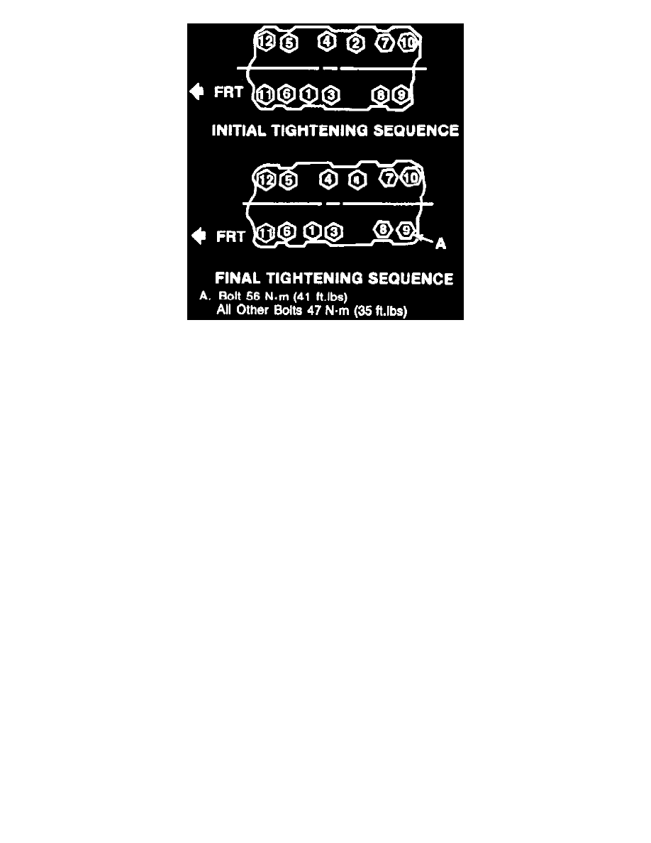
Fig. 5 Intake Manifold Bolt Tightening Sequence
1. Disconnect battery ground cable.
2. Remove engine cover, air cleaner and heat stove tube.
3. Drain cooling system, then remove distributor assembly.
4. Remove cruise control transducer, if equipped.
5. Disconnect cruise control, TVS and accelerator cables, as required.
6. On models equipped with A/C, disconnect A/C compressor and position aside.
7. Remove engine oil filler tube from the alternator bracket.
8. Remove transmission dipstick tube from manifold, if equipped.
9. Remove idler pulley bracket and alternator brackets from manifold.
10. Disconnect fuel and vacuum lines and all electrical connectors from manifold and TBI unit.
11. Remove heater pipe, upper radiator hose, then the power brake vacuum pipe.
12. Disconnect coil wires, then the EGR vacuum line.
13. Disconnect sensors with bracket and wire harness form right side.
14. Remove intake manifold attaching bolts, then the intake manifold.
15. Reverse procedure to install, noting the following:
a. Remove all traces of old sealant from cylinder head, block and manifold.
b. Install gaskets on cylinder heads and apply a 3/16 inch bead of RTV sealant to front and rear ridges of cylinder case. Extend sealant 1/2 inch
up each cylinder head to seal and retain side gaskets.
c. Torque manifold attaching bolt A to 41 ft. lbs. and all other bolts to 35 ft. lbs. in sequence shown in Fig. 8. and.