
Astro Van L AWD V6-262 4.3L VIN Z (1994)
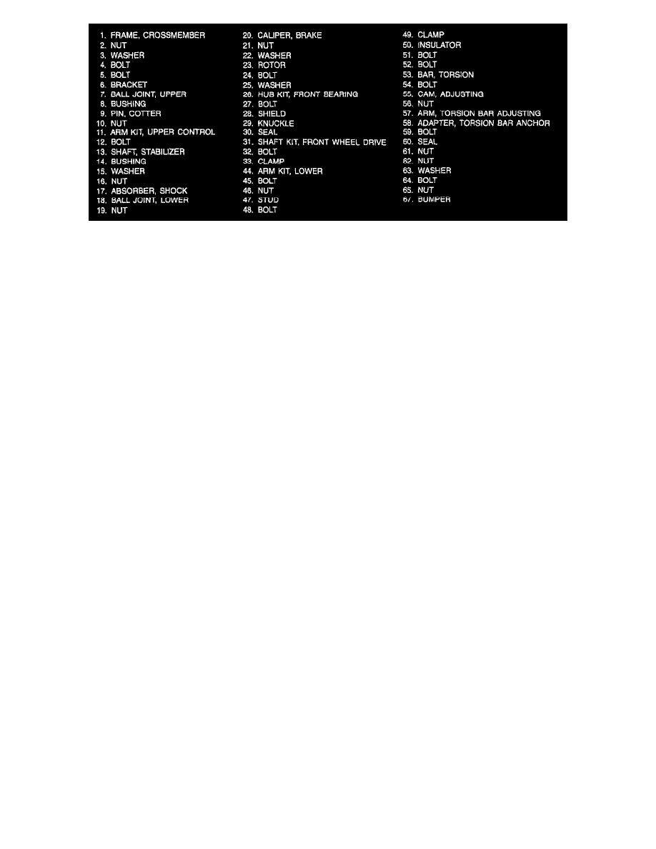
Figure 41
Remove or Disconnect
Tool Required:
J 36607 Ball Joint Separator
-
Two-thirds of the fluid from the brake reservoir.
-
Raise the vehicle.
1. Tire and wheel.
-
Install a cover on the axle joint (31).
2. Brake caliper.
Important: Support the brake caliper with a piece of wire to prevent damage to the brake line.
3. Brake rotor.
4. Drive axle nut (21).
5. Washer (22).
6. Tie rod end nut.
7. Tie rod end from the knuckle (26), using a puller.
9. Drive axle.
10. Splash shield bolts (27).
11. Splash shield (28).
12. Upper ball joint nut (10).
13. Upper ball joint (7) from the knuckle (29).
14. Lower ball joint nut (19).
15. Lower ball joint (18) from the knuckle (29).
16. Knuckle (29).
17. Seal from the knuckle (30).
Install or Connect
Tool Required:
J 36605 Steering Knuckle Seal Installer
1. Seal (30) into the knuckle (29), using J 36605.
2. Knuckle (29) to the upper and lower ball joints (7 and 18).
3. Nuts (10).
4. Nuts (19). Tighten nuts (19) to 128 Nm (95 ft. lbs.). Tighten nuts (10) to 90 Nm (66 ft. lbs.). Tighten the nuts to align the cotter pin. Do not
tighten more than 1/6 turn.
5. New cotter pins (9). Bend the pin ends against the nut flats.
6. Splash shield (28). Be sure the splash shield is aligned properly.
7. Splash shield bolts (27). Tighten bolts (27) to 16 Nm (12 ft. lbs.).
8. Drive axle.
9. Hub and bearing assembly (26). Align the thread holes.
10. Bolts (24). Tighten bolts (24) to 90 Nm (66 ft. lbs.).
11. Tie rod to the knuckle (29).
12. Tie rod end nut.