
Astro Van L AWD V6-262 4.3L VIN Z (1994)
Knock Sensor: Description and Operation
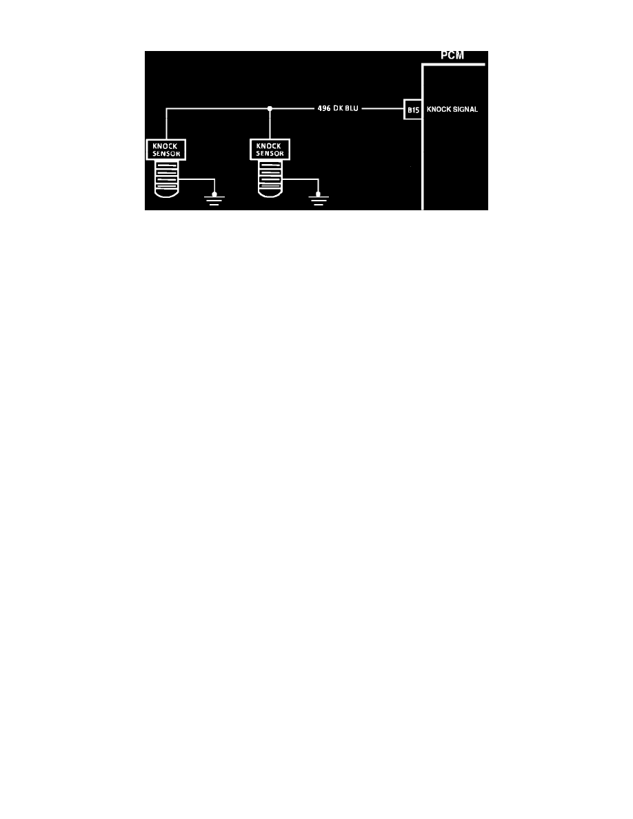
Knock Sensor (KS) Circuit Diagram
NOTE: Because different models and engine applications vary in wire colors, circuit numbers, and pin numbers, the above image is a typical example.
Refer to COMPUTERS AND CONTROL SYSTEMS/SCHEMATIC AND ROUTING DIAGRAMS for specific schematic applications.
PURPOSE:
The knock sensor is located in the engine block and sends a signal to the control module to retard ignition timing during a spark knock condition. When
the knock sensor senses no more knocking the control module advances timing in small increments. This allows the control module to maintain
maximum timing advance under various conditions.