
Astro Van L AWD V6-262 4.3L VIN Z (1994)
4. Coil assembly (3) wire harness through column. Let coil hang freely.
5. Turn signal switch assembly (15) wire harness through steering column.
a). Wire protector (43).
b). Connector body bracket (56) with hexagon nut (57). Tighten nut (57) to 4.0 N-m (35 lb.in.).
c). Turn signal switch (15) connector to vehicle wire harness and connector body bracket (56).
6. Turn signal switch assembly (15) with screws (12). Tighten screws (12) to 3.4 N-m (30 lb.in.).
7. Switch actuator arm (14) and screw (13). Tighten screw (13) to 2.3 N-m (20 lb.in.).
8. Hazard knob assembly and multi-function lever.
9. Thrust washer (17).
10. Upper bearing spring (11).
11. Turn signal cancel cam assembly (10). Lubricate with grease, synthetic (service kit).
12. Shaft lock (9).
13. New shaft lock retaining ring (8) using J 23653-SIR to push down shaft lock (9). Ring (8) must be firmly seated in groove on shaft.
14. Shaft lock spacer (7).
NOTICE: Set steering shaft so that block tooth on upper steering shaft (46) is at the 12 o'clock position, wheels on vehicle should be straight ahead,
then set ignition switch to "LOCK" position, to ensure no damage to coil assembly (3).
15. Wave washer (4).
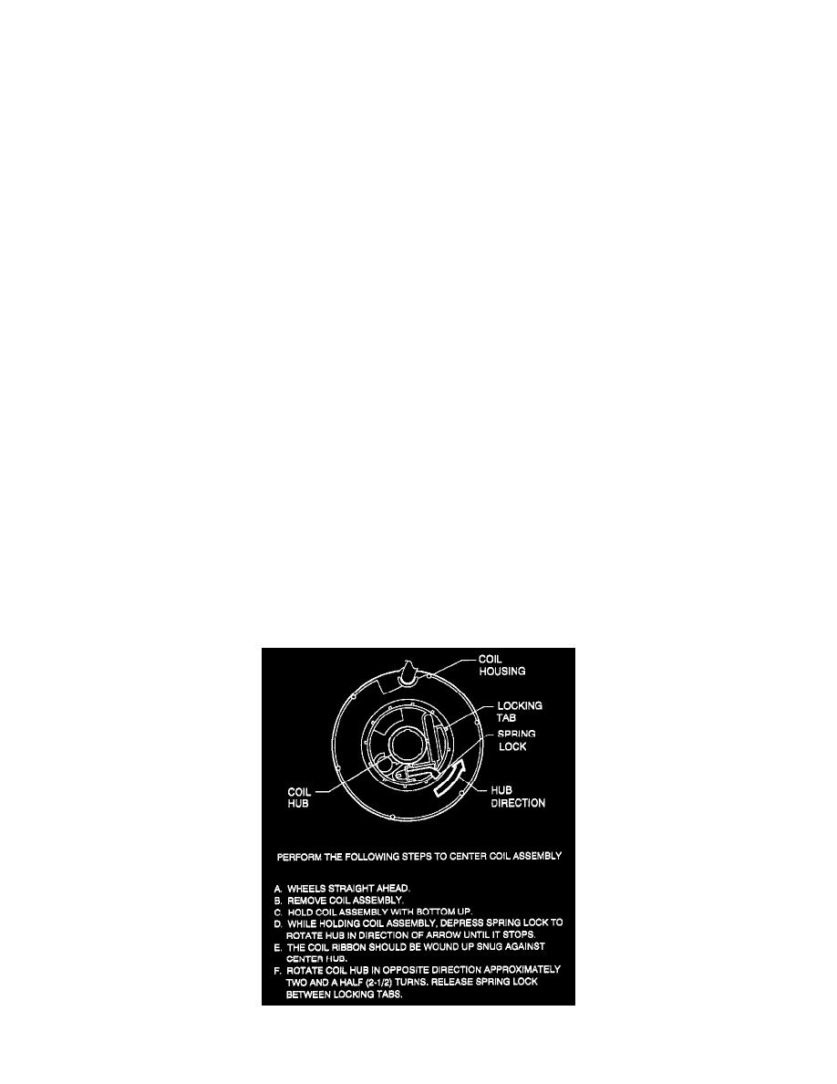
NOTICE: Coil assembly (3) will become uncentered if:
1) Steering column is separated from steering gear and is allowed to rotate, or
2) Centering spring is pushed down, letting hub rotate while coil is removed from column.
NOTICE: If a new coil assembly (3) is being installed, assemble pre-centered coil assembly (3) to steering column. Remove centering tab and