
Astro Van M L4-151 2.5L (1985)
First Stop:
Stop vehicle from 40 mph by applying the brakes to achieve a deceleration rate of 10 ft/sec/sec. (A 10 ft/sec/sec deceleration is
equivalent to stopping the vehicle from 40 mph in 6 seconds.)
Second through Eleventh Stops:
Stop vehicle from 50 mph by applying the brakes to achieve a deceleration rate of 15 ft/sec/sec. (A 15
ft/sec/sec deceleration is equivalent to stopping the vehicle from 50 mph in 5 seconds.)
Twelfth Stop:
Stop vehicle from 40 mph by applying the brakes to achieve a deceleration rate of 10 ft/sec/sec.
In order to allow brake temperatures to stabilize, it will be necessary to drive 1/2 mile between stops without applying brakes. Following
completion of burnish procedure (twelfth stop), drive vehicle 3 miles keeping brake usage to a minimum in order to achieve sufficient brake cool
down.
Service Procedure 1987 Models
1987 MODELS
Effective 1987 start of production, all Astro models were manufactured with new wheel cylinders described earlier in this bulletin; however, the new
combination valve was not installed in the first several months of production. The new combination valve was installed effective with the following
Vehicle Identification Number:
VIN HB137507
1987 vehicles produced prior to this VIN breakpoint can be modified by following the service procedure listed below:
SERVICE PROCEDURE
1987 Model 2.5L TBI and 4.3L TBI Engines
Note:
Care must be taken to prevent brake fluid from contacting any painted surface.
Always ensure that the brake system is operational after performing brake work and before returning the vehicle to the customer.
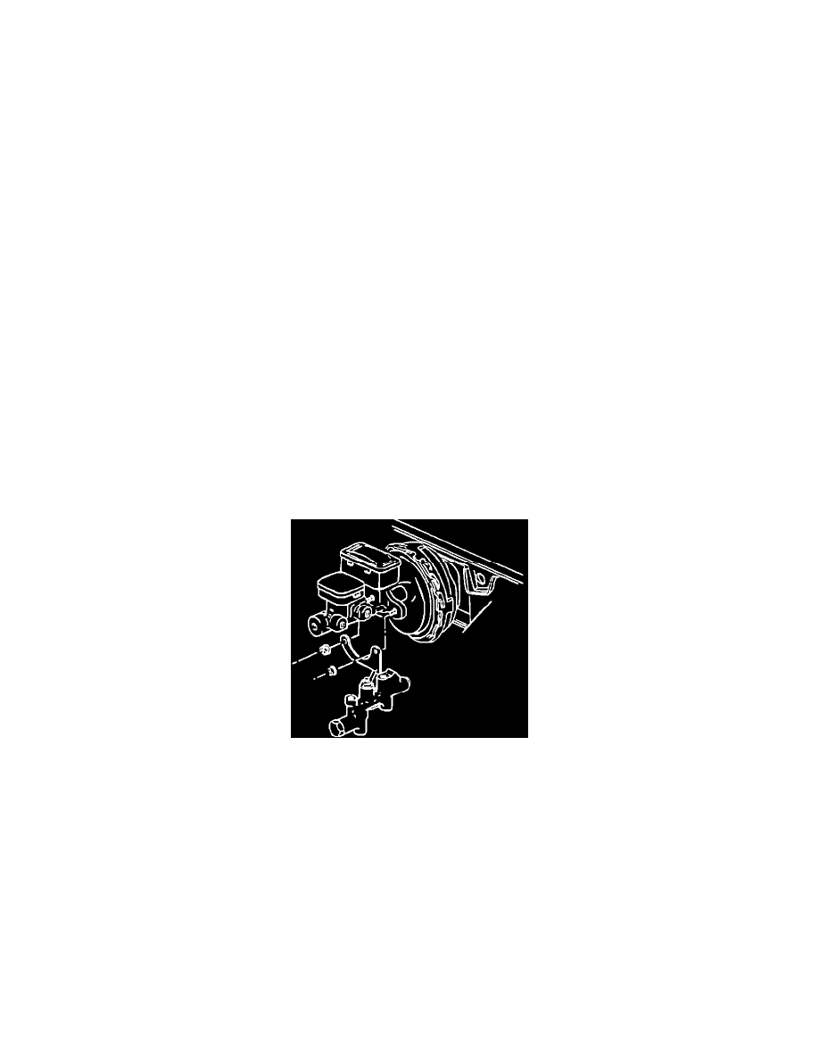
FIGURE 1 - COMBINATION VALVE
Replacement of the combination valve, Figure No. 1.
1.
Disconnect negative battery cable.
2.
Disconnect the four brake lines at the combination valve.
3.
Disconnect electrical harness at the combination valve.
4.
Disconnect combination valve at bracket on the brake booster and discard valve.
5.
Install new combination valve (P/N 15571205)
6.
Reverse above procedure for reinstallation and tighten bracket nuts to 50 N-m (37 ft.lbs.).
7.
Reinstall brake lines and torque nuts to 25 N-m (18 ft. lbs.).
Parts List
1.
Combination Valve (1) P/N 15571205
2.
Wheel Cylinders (2) P/N 18004888
3.
Brake Shoe Kit (1) P/N 12321427
4.
Link Pin Kit (2) P/N 5464748
5.
Brake Fluid DOT 3 P/N 1052535