
Astro Van M L4-151 2.5L (1985)
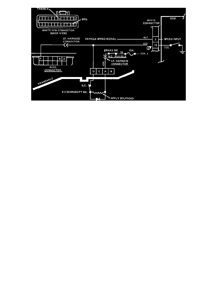
Wiring Diagram For Chart C-8A - TCC System Diagnosis
CHART C-8A - TRANSMISSION CONVERTER CLUTCH (TCC)
Circuit Description:
The purpose of the automatic transmission torque converter clutch feature is to eliminate the power loss of the torque converter stage when the vehicle is
in a cruise condition. This allows the convenience of the automatic transmission and the fuel economy of a manual transmission.
Fused battery ignition is supplied to the TCC solenoid through the brake switch, and transmission third gear apply switch. The ECM will engage TCC by
grounding CKT 422 to energize the solenoid.
TCC will engage when:
-
Vehicle speed above 45 MPH (72 km/h)
-
Engine at normal operating temperature above 70~C (158~F)
-
Throttle position sensor output not changing, indicating a steady road speed.
-
Transmission third gear switch closed
-
Brake switch closed
Test Description:
1.
Checks continuity through brake switch, TCC solenoid, and 4-3 downshift switch.
2.
Checks capability of ECM to energize solenoid. Grounding the diagnostic connector should energize the relay and cause the light to go out.
3.
This test by-passes the TCC solenoid and 4-3 switch and checks for an open or short in CKT 422.
4.
Solenoids are turned "ON" or "OFF" by the ECM internal electronic switches called "drivers". Each driver is part of a group of four called
"Quad-Drivers". Failure of one can damage any other driver within the set. Solenoid coil resistance must measure more than 20 ohms. Less
resistance will cause early failure of the ECM "DRIVER". Using an ohmmeter, check the solenoid coil resistance before install a replacement ECM.
^
TCC Solenoid