
Avalanche 1500 2WD V8-5.3L (2008)
hub/axle flange and the brake rotor mating surfaces. Failure to do this may result in excessive assembled lateral runout (LRO) of the brake rotor,
which could lead to brake pulsation.
1. Use the J 42450-A to clean all rust and contaminants from the mating surface of the hub flange.
2. Use the J 41013 to clean all rust and contaminants from the inside diameter of the hat section of the brake rotor to prevent any foreign material
from getting between the brake rotor and the hub flange.
3. Inspect the mating surfaces of the hub/axle flange and the rotor to ensure that there are no foreign particles or debris remaining.
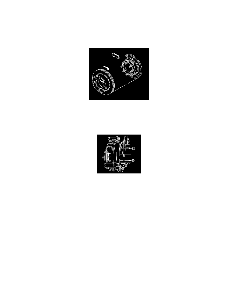
4. Align the rotor to its original position on the hub, if applicable.
5. Install the rotor by slowly turning the rotor while pushing the rotor towards the axle.
6. If the rotor was removed and installed as part of a brake system repair, measure the assembled lateral runout (LRO) of the rotor to ensure optimum
performance of the disc brakes. Refer to Brake Rotor Assembled Lateral Runout Measurement (See: Testing and Inspection/Brake Rotor
Assembled Lateral Runout Measurement) .
7. If the rotor assembled LRO measurement exceeds the specification, bring the LRO to within specifications. Refer to Brake Rotor Assembled
Lateral Runout Correction (See: Testing and Inspection/Brake Rotor Assembled Lateral Runout Correction) .
8. Install the caliper and caliper bracket as an assembly.
9. Perform the following procedure before installing the brake caliper bracket bolts:
1. Remove all traces of the original adhesive patch.
2. Clean the threads of the bolts with brake parts cleaner or the equivalent and allow to dry.
3. Apply threadlocker GM P/N 12345493 (Canadian P/N 10953488) to the threads of the bolts.
Notice: Refer to Fastener Notice .
10. Install the brake caliper bracket bolts.
Tighten the bolts to 200 N.m (148 lb ft).
11. Install the tire and wheel assembly. Refer to Tire and Wheel Removal and Installation .
12. Lower the vehicle.
13. With the engine OFF gradually apply the brake pedal to approximately 2/3 of its travel distance.
14. Slowly release the brake pedal.
15. Wait 15 seconds then repeat steps 13-14 until a firm pedal is obtained. This will properly seat the caliper pistons and pads.
16. Fill the master cylinder reservoir to the proper level with clean brake fluid, if necessary. Refer to Master Cylinder Reservoir Filling (See:
Hydraulic System/Brake Master Cylinder/Service and Repair/Procedures/Master Cylinder Reservoir Filling) .
Brake Pad and Rotor Burnishing
Brake Pad and Rotor Burnishing
Caution: Refer to Road Test Caution .
Burnishing the brake pads and brake rotors is necessary in order to ensure that the braking surfaces are properly prepared after service has been