
Aveo L4-1.6L (2008)
Fuel Injector: Testing and Inspection
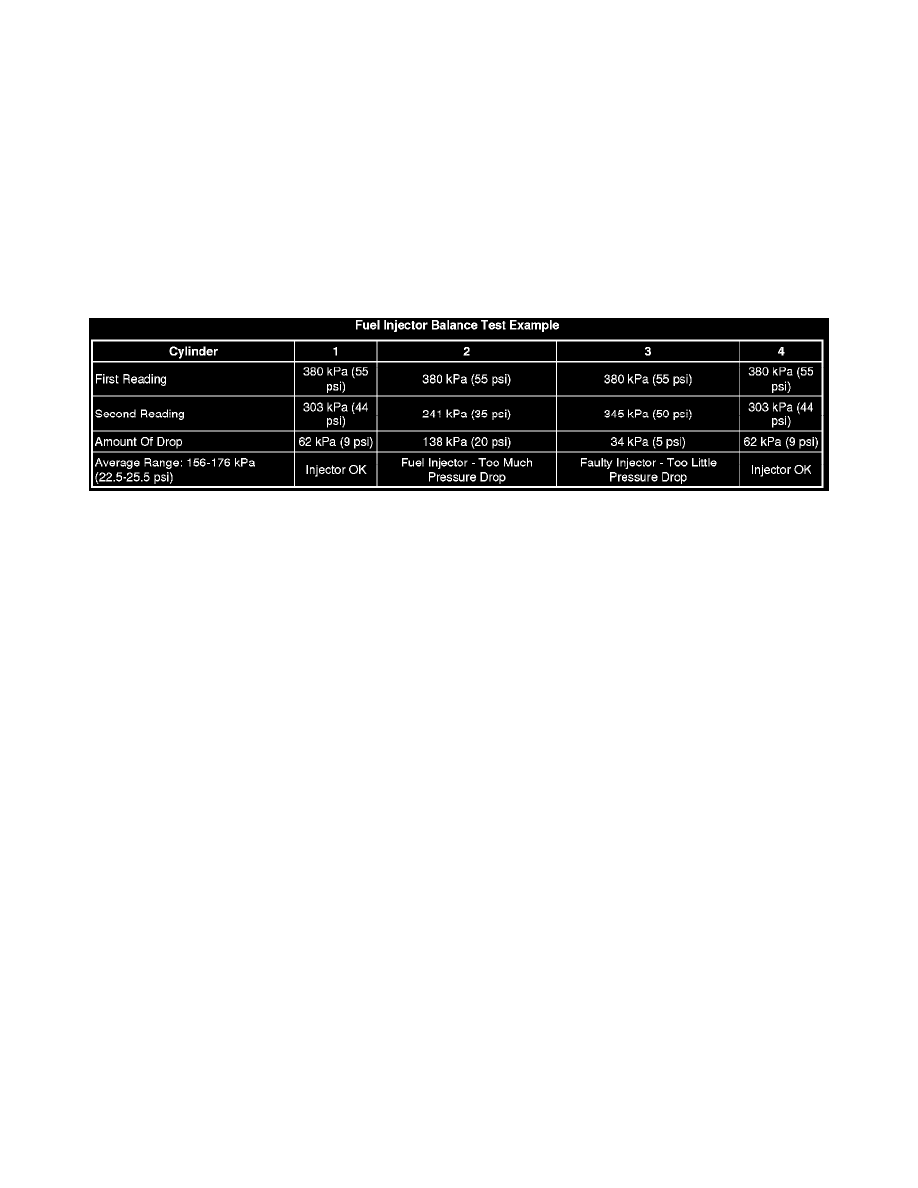
Fuel Injector Balance Test With Special Tool
Fuel Injector Balance Test with Special Tool
Diagnostic Instructions
*
Perform the Diagnostic System Check - Vehicle (See: Testing and Inspection/Initial Inspection and Diagnostic Overview/Diagnostic System
Check - Vehicle) prior to using this diagnostic procedure.
*
Review Strategy Based Diagnosis (See: Testing and Inspection/Initial Inspection and Diagnostic Overview/Strategy Based Diagnosis) for an
overview of the diagnostic approach.
*
Diagnostic Procedure Instructions (See: Testing and Inspection/Initial Inspection and Diagnostic Overview/Diagnostic Procedure Instructions)
provides an overview of each diagnostic category.
Diagnostic Fault Information
Circuit/System Description
The scan tool is first used to energize the fuel pump relay. The fuel injector tester is then used to pulse each injector for a precise amount of time,
allowing a measured amount of fuel into the manifold. This causes a drop in system fuel pressure that can be recorded and used to compare each injector.
Diagnostic Aids
*
Monitoring the misfire current counters, or misfire graph, may help to isolate the fuel injector that is causing the condition.
*
Operating the vehicle over a wide temperature range may help isolate the fuel injector that is causing the condition.
*
Perform the fuel injector balance test within the conditions of the customers concern. A fuel injector condition may only be apparent at a certain
temperature, or under certain conditions.
Reference Information
Schematic Reference
Engine Controls Schematics (MR140 w/o Throttle Actuator Control) (See: Diagrams/Electrical Diagrams/Engine Controls Diagrams (MR140 w/o
Throttle Actuator Control))Engine Controls Schematics (MT34 w/Throttle Actuator Control) (See: Diagrams/Electrical Diagrams/Engine Controls
Diagrams (MT34 w/Throttle Actuator Control))Engine Controls Schematics (Hatchback) (See: Diagrams/Electrical Diagrams/Engine Controls Diagrams
(Hatchback))
Description and Operation
Fuel System Description (See: Computers and Control Systems/Description and Operation/Fuel System Description)
Scan Tool Reference
Control Module References (See: Testing and Inspection/Programming and Relearning) for scan tool information
Special Tools
J 39021 Fuel Injector Coil and Balance Tester
Component Testing
Fuel Injector Balance Test with Special Tool
1. Ignition ON, verify the scan tool engine coolant temperature (ECT) parameter is less than 94°C (201°F).
‹› If greater thanes specified range, allow the engine to cool before proceeding.
2. Ignition OFF, install the fuel pressure gage. Refer to Fuel Pressure Gage Installation and Removal (See: Fuel Pressure/Testing and Inspection/Fuel
Pressure Gage Installation and Removal).