
Beretta L4-138 2.3L DOHC QUAD 4 HO MFI VIN A (1994)
Ignition Control Module: Service and Repair
REMOVAL
1.
Remove negative battery cable.
2.
Disconnect 11 pin IDIS harness connector.
3.
Remove ignition system assembly to cam housing bolts (4).
4.
Remove ignition system assembly from engine.
5.
Remove housing to cover screws (4).
6.
Remove housing from cover.
7.
Disconnect coil harness connector from module.
8.
Remove module to cover screws (3).
9.
Remove module from cover.
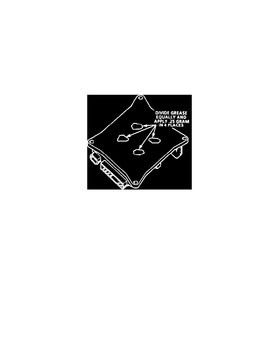
NOTE: DO NOT wipe grease from module or coil if same module is to be replaced. If a new module is to be installed, a package of silicone
grease will be included with it. Spread the grease on the metal face of the module and on the cover where the module seats. This grease is
necessary for module cooling.
Dielectric Grease Application
INSTALLATION
1.
Install module to cover.
2.
Install module to cover screws (3). Torque to 4 N-m (35 lb. in.).
3.
Connect coil harness connector to module.
4.
Install housing to cover.
5.
Install housing to cover screws (4). Torque to 4 N-m (35 lb. in.).
6.
Connect spark plug boots and retainers to housing.
7.
Install ignition system assembly to engine while carefully aligning boots to spark plug terminals.
8.
Install ignition system assembly to cam housing bolts after coating threads with 1052080 or equivalent (4). Torque to 26 N-m (19 lb. ft.).
9.
Connect 11 pin IDI harness connector.
10.
Connect negative battery cable.