
Beretta V6-3100 3.1L VIN M SFI (1995)
Throttle Position Sensor: Testing and Inspection
Throttle Position Sensor Installation
DIAGNOSIS
A Tech 1 scan tool displays Throttle Position (TP) in volts. Voltage should increase at a steady rate as throttle is moved toward Wide Open
Throttle (WOT).
The Powertrain Control Module (PCM) has the ability to auto-zero the TP sensor voltage if it is between 0.29 volt (290 mV) and 0.98 volt (980
mV). This means that any voltage between 0.29 and 0.98 volt will be determined by the PCM to be 0% throttle. Tech 1 scan tools have the ability
to read the throttle angle and should display 0% when the throttle is closed.
If the throttle angle at idle displayed on the Tech 1 at a value greater than 1%, check for cable binding or a stuck throttle valve. If there is no
mechanical fault, remove power from the PCM for 20 seconds. This will clear throttle angle from memory. Restore PCM power and then monitor
throttle angle with the Tech 1 at idle. If the value indicated is still greater than 1% at idle, the TP sensor or PCM may be at fault.A failure in the TP
sensor or circuit should set a DTC 21 or 22.
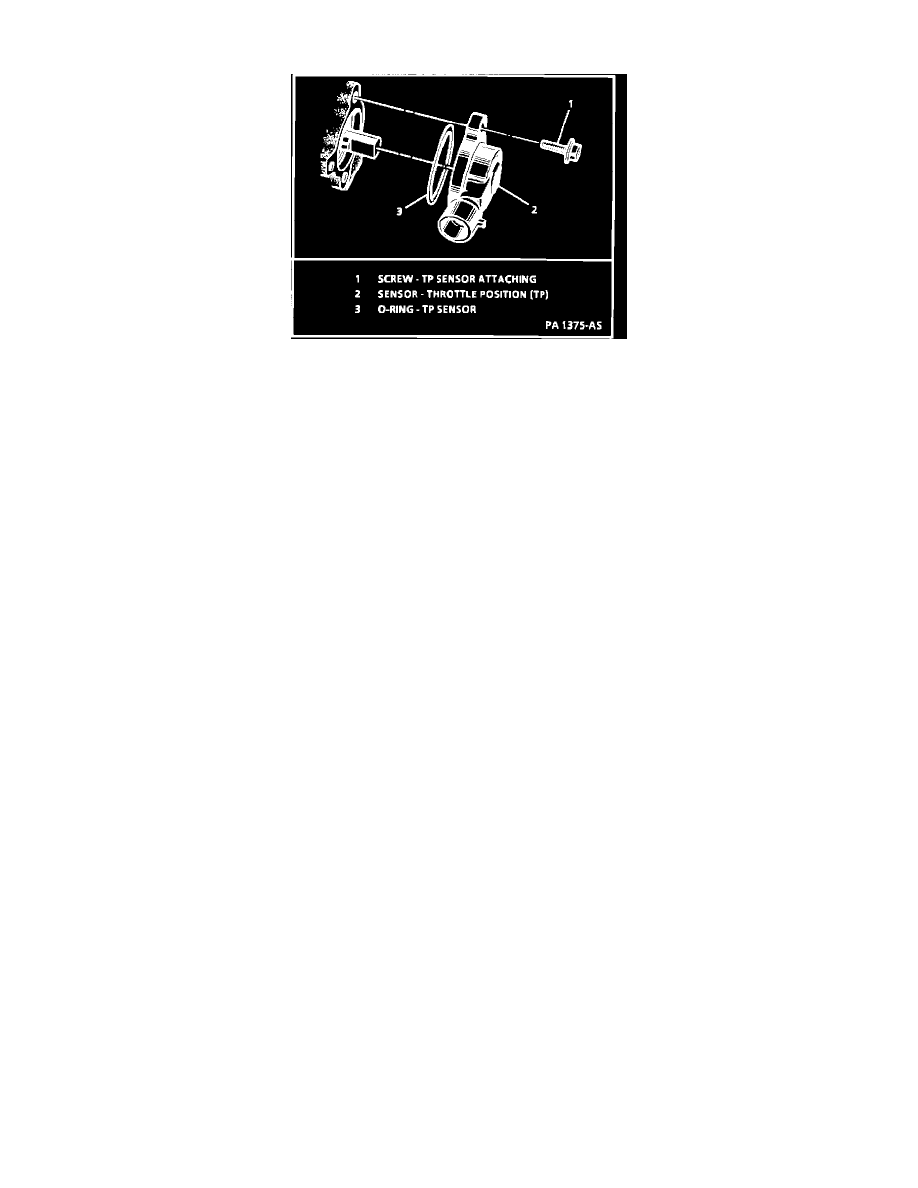
REMOVE OR DISCONNECT
1. TP sensor electrical connector.
2. TP sensor attaching screws and retainers.
3. Sensor and 0-ring.
INSTALL OR CONNECT
1. With throttle valve in the normal closed idle position, install TP sensor on throttle body assembly.
2. Two TP sensor screws. Tighten to 2.0 Nm (18.0 lb in).
3. TP sensor electrical connector.