
C 1500 Suburban 2WD V8-4.8L VIN V (2002)
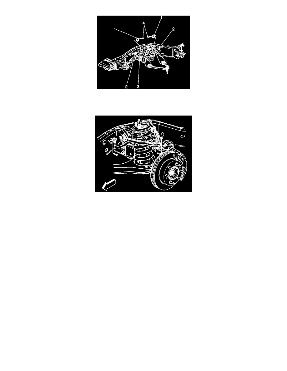
4. Install the upper control arm bolts (4) for the 15 Series 2WD, 4WD, and 25/35 Series 2WD.
5. Install the upper control arm nuts and the adjustment cams (2) for the 15 Series 2WD, 4WD, and 25/35 Series 2WD.
Tighten the nuts to 190 Nm (140 ft. lbs.).
6. Connect the upper control arm to the steering knuckle.
7. Install the wheel drive shaft.
8. Install the new nut to the upper ball joint stud.
Tighten the nut to 50 Nm (37 ft. lbs.).
9. Install the retaining bolts for the brake hose and wheel speed sensor brackets.
Tighten the bolts to 9 Nm (80 inch lbs.).
10. Connect the RTD link rod to the sensor, if equipped.
11. Install the tire and wheel.
12. Remove the safety stands.
13. Lower the vehicle.
14. Verify the wheel alignment.
Lower Control Arm Replacement
Lower Control Arm Replacement
Tools Required
^
J43631 Ball Joint Separator
Removal Procedure
1. Raise and support the vehicle. Refer to Vehicle Lifting.
2. Remove the tire and wheel.
3. Disconnect the Real Time Damping (RTD) link rod from the sensor, if equipped.