
C 20 P/U 2WD V8-305 5.0L (1985)
shaft and gauge tang must be positioned in valve mounting hole (Figure No. 2).
^
Reinstall lever assembly to the valve shaft utilizing a "C" clamp or channel lock pliers to seat lever nylon bushing to serration on the valve shaft.
Note:
DO NOT DRIVE THE LEVER ONTO THE SHAFT USING THE ATTACHING NUT. DOING SO MAY RESULT IN IMPROPER VALVE
SETTING.
^
Reinstall valve shaft nut and torque to 8 - 11 N-m. (70-98 in.lbs.)
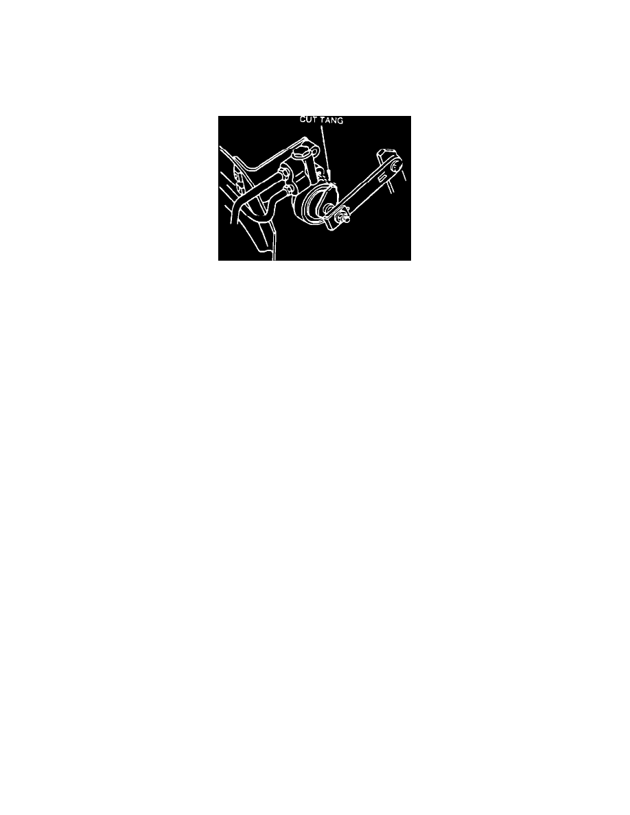
Cut gauge tang from body
^
Cut gauge tang from body of the adjustment gauge to allow the valve assembly to rotate freely (Figure No. 3).
^
Lower vehicle and test brakes.
PARTS INFORMATION
Model
P/N
Description
Code
Color
C20906
14061394
Gauge
A
Green
K20906
15548904
Gauge
E
Yellow
BRAKE BURNISHING
^
On dry clean level roadway, accelerate to 55 mph., observe traffic following and when its clear
^
Apply brake at a deceleration rate of 8 ft/sec/sec/ until vehicle speed is 25 mph. A decelerometer must be used to achieve the proper
deceleration rate.
^
Repeat this procedure at 1 mile intervals 15 times.
Decelerometers are available from various sources, one of which is:
Ammco Tool Company 2100 Commonwealth Avenue
N.
Chicago, IL 60064