
C 2500 Truck 2WD V8-5.7L VIN R (1997)
VCM REPLACEMENT/PROGRAMMING
Service of the VCM consists of either replacement of VCM or reprogramming of the EEPROM. If the diagnostics call for replacement of the VCM, it
will be necessary to transfer the PROM and program the EEPROM.
NOTE: When replacing the production VCM with a service VCM (controller), it is important to transfer the broadcast code and production VCM
number to the service VCM label. This will allow positive identification of VCM parts throughout the service life of the vehicle. Also transfer the
PROM.
CAUTION: To prevent internal VCM damage, the ignition must be OFF when disconnecting or reconnecting power to the VCM (for example, battery
cable, VCM fuse, jumper cables, etc.).
CAUTION: In order to prevent possible Electrostatic Discharge damage to the VCM, do not touch the connector pins or soldered components on the
circuit board.
VCM REPLACEMENT/PROGRAMMING (WITH KNOCK SENSOR (KS) CALIBRATION PROM)
REMOVAL PROCEDURE
1. Disconnect the negative battery cable.
2. Remove the connectors from the VCM.
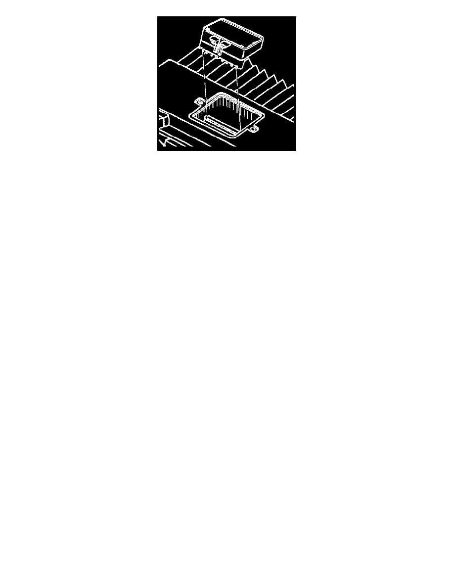
3. Remove the spring retainer off and over the rail of the VCM. Slide the VCM out of the bracket at an angle.
4. Remove the VCM access cover.
5. Remove the PROM/Knock Sensor (KS) module.
6. Inspect for the alignment notches of the KS Calibration PROM.
7. Carefully set it aside.
8. Do not open the KS Calibration PROM.
9. Remove the new VCM from the packaging. Check the service number in order to make sure it is the same as the defective VCM.
10. Remove the access cover.
NOTE
^
The Knock Sensor (KS) module must be transferred to the replacement VCM.
^
The replacement VCM is supplied without a EEPROM program, the replacement VCM must be programmed before the vehicle will run.
^
Using the thumb and first finger, remove the KS Calibration PROM by gently squeezing each end of the blue KS Calibration PROM
^
Do not remove the cover of the KS Calibration PROM. Use of an unapproved KS Calibration PROM removal methods may cause damage to
the KS Calibration PROM or the socket.
INSTALLATION PROCEDURE
NOTE: Press only on the ends of the KS Calibration PROM. Gently press on the KS Calibration PROM until it is firmly seated in the socket. Listen for
the click.
1. Align the notches of the KS Calibration PROM with the notches in the KS Calibration PROM socket.
2. Install the KS Calibration PROM in the KS Calibration PROM socket.
3. Install the access cover on the VCM.
4. Install the VCM in the engine compartment.
5. Install the connectors to the VCM.
6. The MIL, antilock and brake lamps will continue to be enabled until the VCM is programmed. Once the programming is complete, the lamps will
turn off and normal operation will occur.
7. Connect the negative battery cable.