
C 2500 Truck 2WD V8-5.7L VIN R (1997)
Knock Sensor: Service and Repair
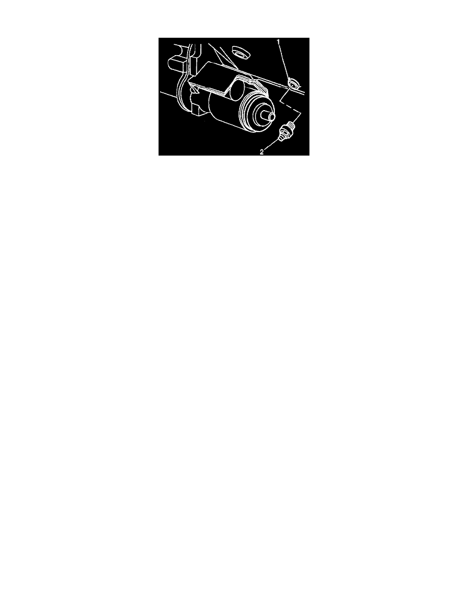
Diagram
Removal Procedure
NOTE: The knock sensor is located in areas of the cylinder head. On most applications, the knock sensors are installed in a hole which is exposed to
engine coolant. Care should be exercised when servicing these sensors.
1. Disconnect the negative battery cable.
Important: On knock sensors which are mounted in the end of the cylinder head draining the cooling system will not be necessary.
2. Drain the cooling system. Refer to Draining and Filling Cooling System.
3. Remove the wiring harness connector from knock sensor.
4. Remove the knock sensor from cylinder head.
Installation Procedure
Important: Do not use silicon tape as this will insulate the sensor from the engine block.
2. After applying a water base caulk to the sensor threads, install the knock sensor into the cylinder head.
Tighten
^
Tighten to 19 Nm (14 lb. ft.).
2. Connect the negative battery cable.
3. Refill cooling system if required. Refer to Draining and Filling Cooling System.