
C 3500 HD Truck 2WD V8-6.5L DSL Turbo VIN F (2001)
Connecting Rod Bearing: Service and Repair
^
Tools Required
-
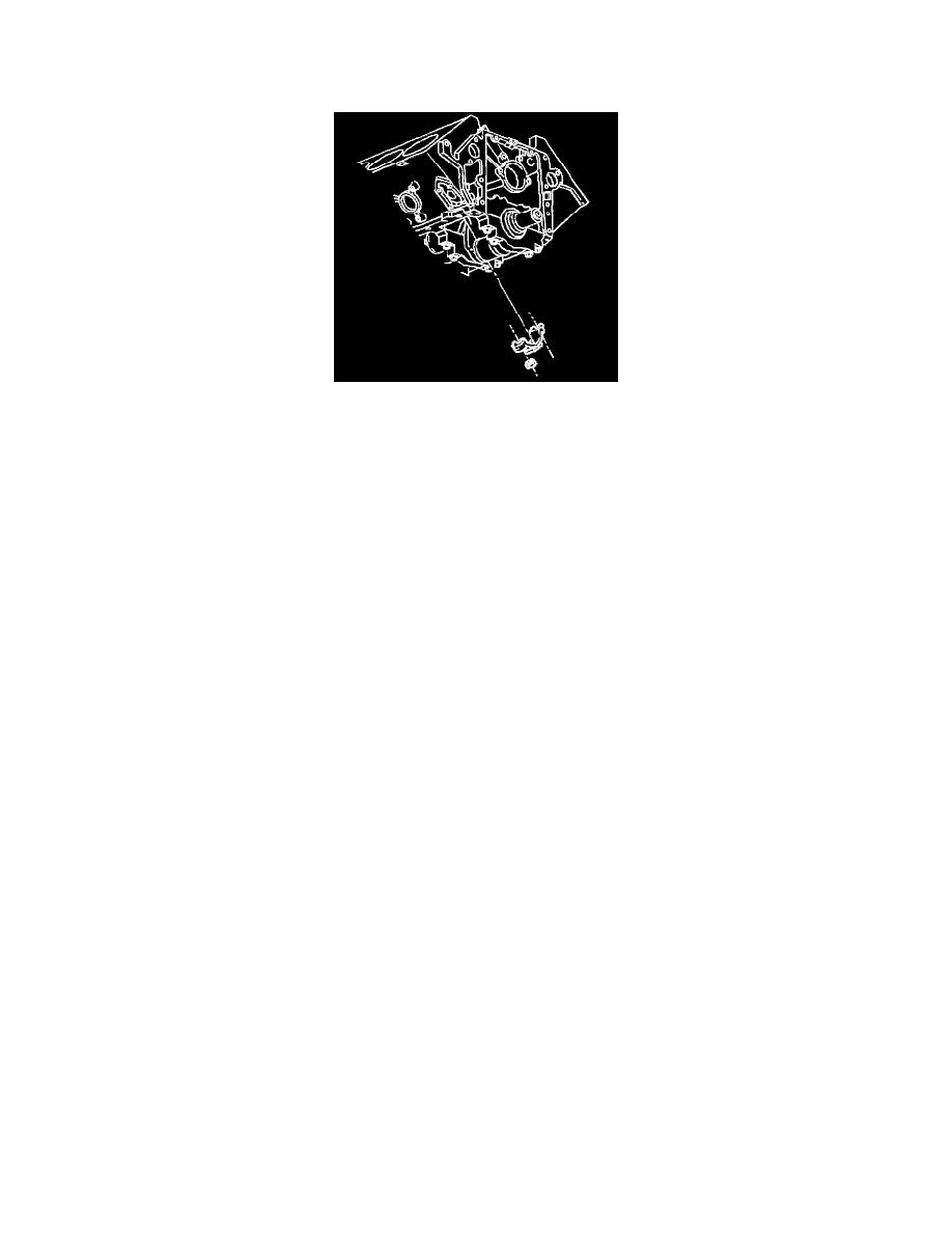
J8037 Ring Compressor
The connecting rod bearings are precision insert connecting rod bearings, and do not require shims for adjustment. Do not file the rods or the rod caps.
If the engine has excessive clearances, install a new bearing. Service bearings are available in standards size, with yellow color for identification, and
0.026 mm (0.001 inch) undersized, with green color for identification. Selective fitting of the rod and the crankshaft is necessary in order to obtain
close tolerances. For example, use one-half of a 0.026 mm (0.0010 inch) undersized insert, which will decrease the clearance by 0.013 mm (0.0005
inch), rather than using a full standard bearing.
Important:
^
When using selective fit rod bearings, always use the standard bearing in the connecting rod, and use the undersized bearing in the end of the rod
cap.
^
Note that the color-coding for selective fit rod bearings is different from the color-coding for the crankshaft bearings.
^
Connecting rod bearings are available in 0.026 mm (0.0010 inch) undersized for select fitting.
^
The L65 engines may have both, standard and 0.08 mm (0.0010 inch) oversize connecting rod bearings. The oversize connecting rod cap's lower
end is stamped with OS.
Important:
^
Make sure that the cylinder walls are clean.
^
Lightly lubricate the cylinder walls with engine oil.
^
Make sure that the pistons install in their matching cylinder.
-
Install used pistons in the cylinders from which they were removed.
-
Install new pistons in their fitted cylinders.
1. Remove the connecting rod cap from the piston and connecting rod assembly.
2. Install two 10 mm (3/8 inch) hose onto the connecting rod studs.
3. Locate the piston ring end gaps, with the piston viewed with the swirl indent up, in the following way:
3.1.
The oil ring expander gap at 45 degrees left of the swirl indent
3.2.
The oil control ring gaps at 180 degrees opposite of the oil expander ring
3.3.
The second compression ring gap at the piston top and under the swirl indent
3.4.
The first compression ring 180 degrees opposite of the second ring. Lubricate the piston and rings with engine oil.
4. Without disturbing the ring end gap location, install the J8037.