
C 3500 HD Truck 2WD V8-6.5L DSL Turbo VIN F (2001)
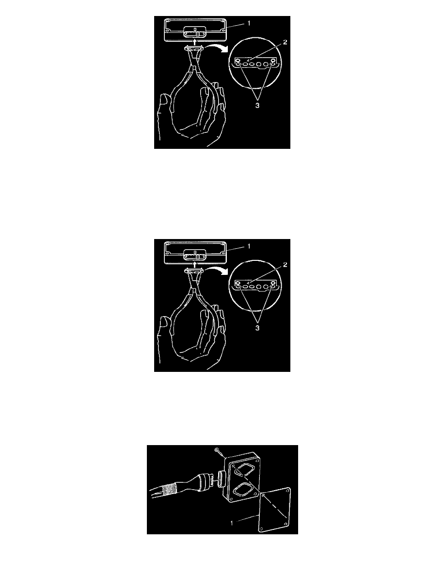
9. Remove the fuel solenoid calibrating resistor using a snap ring pliers. The calibrating resistor is located on a small circuit board which is located in
the PMD connector housing and is placed over the PMD terminal pins. This calibrating resistor circuit board has two outboard holes (3) which can
be grabbed with snap ring pliers.
INSTALLATION PROCEDURE
IMPORTANT: The calibrating resistor is specific to the injection pump. Do not damage the resistor. The calibrating resistor indication number (2) is
located on the front of the calibrating resistor. If the calibrating resistor is damaged or lost, the injection pump must be removed for replacement or
taken to a Stanadyne dealer for calibration.
1. Install the calibrating resistor in the new fuel solenoid driver using snap ring pliers (the resistor is keyed to fit in only one way). Install the resistor
with the indication number facing upward. If the fuel solenoid driver calibrating resistor is missing, DTC 1218 will set.
IMPORTANT: The pad is designed to transfer heat generated by the PMD to the pump housing so the heat can be dissipated. Do not install the fuel
solenoid driver without a new heat transfer pad. Do not reuse a heat transfer pad. Use a new heat transfer pad only. The heat transfer pad is required to
prevent rapid failure of the fuel solenoid driver from overheating. The heat transfer pad is not a seal or a gasket. The pump comes with new screws
and a new heat transfer pad.
2. Place the new heat transfer pad (1) on the side of the new fuel solenoid driver and insert the four fuel solenoid driver mounting screws into the fuel