
C 3500 Truck 2WD V8-6.0L VIN U (2001)
Housing Assembly HVAC: Description and Operation
HVAC Systems - Automatic
General Descriptions
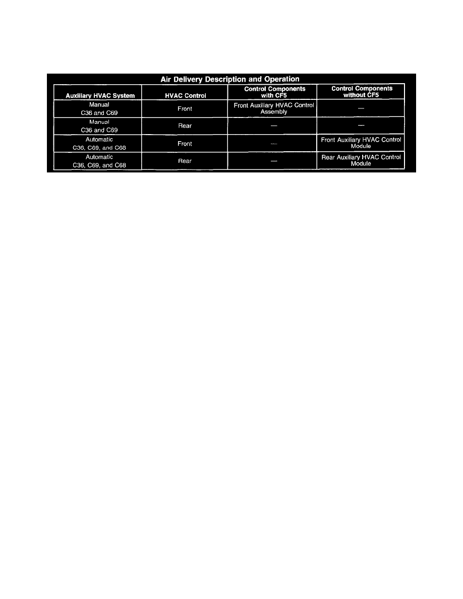
Air Delivery Description And Operation
The air delivery controls are divided into two primary areas:
1. Air speed is dependent upon blower motor speed.
2. Air distribution is related to various single or multiple air outlets.
"For a description of the RPO Code(s) shown in this article or any of the images therein, refer to the RPO Code List found at Vehicle/Application ID".
See: Application and ID/RPO Codes
Auxiliary HVAC Configurations
The Automatic HVAC system has the option of being configured with either a manual or automatic auxiliary system. The number of auxiliary HVAC
controls is dependent upon whether or not the vehicle is equipped with a sunroof (CF5). An automatic auxiliary HVAC system is only available with an
automatic primary HVAC system without a sunroof. A manual auxiliary HVAC system is only available with an automatic auxiliary primary HVAC
system with a sunroof.
The automatic primary and auxiliary HVAC systems communicate using Keyboard Data Display (KDD) protocol. The automatic primary system
communicates with the rear auxiliary HVAC control module. The manual auxiliary system is independent of the automatic primary HVAC system.
"For a description of the RPO Code(s) shown in this article or any of the images therein, refer to the RPO Code List found at Vehicle/Application ID".
See: Application and ID/RPO Codes
Air Speed-Front Control
The blower motor forces air to circulate within the vehicle's interior. The vehicle operator determines the blower motor's speed by placing the blower
motor switch in a desired speed position or by selecting automatic operation. The blower motor will only operate if the blower motor switch is in any
position other than OFF, and the ignition switch is in the RUN position. The blower motor and mode switches are located on the front of the HVAC
control module.
Power is provided to the blower motor from the underhood junction block through the battery positive voltage circuit. The HVAC control module
receives power from the ignition 3 voltage and battery positive voltage circuits. Ground is provided by the right instrument panel junction block through
the ground circuits.
When any blower speed is selected, the HVAC control module sends a Pulse Width Modulated (PWM) signal to the blower motor on the blower speed
control circuit. In manual operation, once a blower speed is selected, the blower speed remains constant until a new speed is selected. In automatic
operation, the HVAC control module will determine what blower speed is necessary in order to achieve or maintain a desired temperature.
Air Speed-Manual Auxiliary HVAC Control
The auxiliary blower motor circulates the air at the rear of the vehicle. The vehicle operator determines the auxiliary blower motor's speed by placing the
blower motor switch in a desired speed position. The auxiliary blower motor switch controls the auxiliary blower motor speed. Three relay blower motor
speed control circuits enable one of three relays to provide power to the blower motor. The blower motor switch grounds the selected relay. Each relay's
control and load power is provided by the ignition and battery positive voltage circuits. Both the low and medium speed relays connect to the auxiliary
blower motor through a resistor assembly. The resistor assembly creates a voltage divider circuit with the auxiliary blower motor to select the auxiliary
blower motor speed. The high speed relay is connected directly to the auxiliary blower motor. The primary HVAC control module located in the dash
does not control the auxiliary HVAC system.
Air Speed-Automatic Auxiliary HVAC Control
The auxiliary blower motor circulates the air at the rear of the vehicle. The auxiliary blower motor can be controlled by either of the auxiliary HVAC
controls. The primary HVAC control module located in the dash does not control the auxiliary HVAC system. If the vehicle does not have a sunroof
(CF5), then the front auxiliary controls must be set to the rear position for the rear auxiliary controls to operate. The vehicle operator determines the
blower motor's speed by placing a blower motor switch in a desired speed position or by selecting automatic operation.