
Camaro V8-305 5.0L VIN F FI (1985)
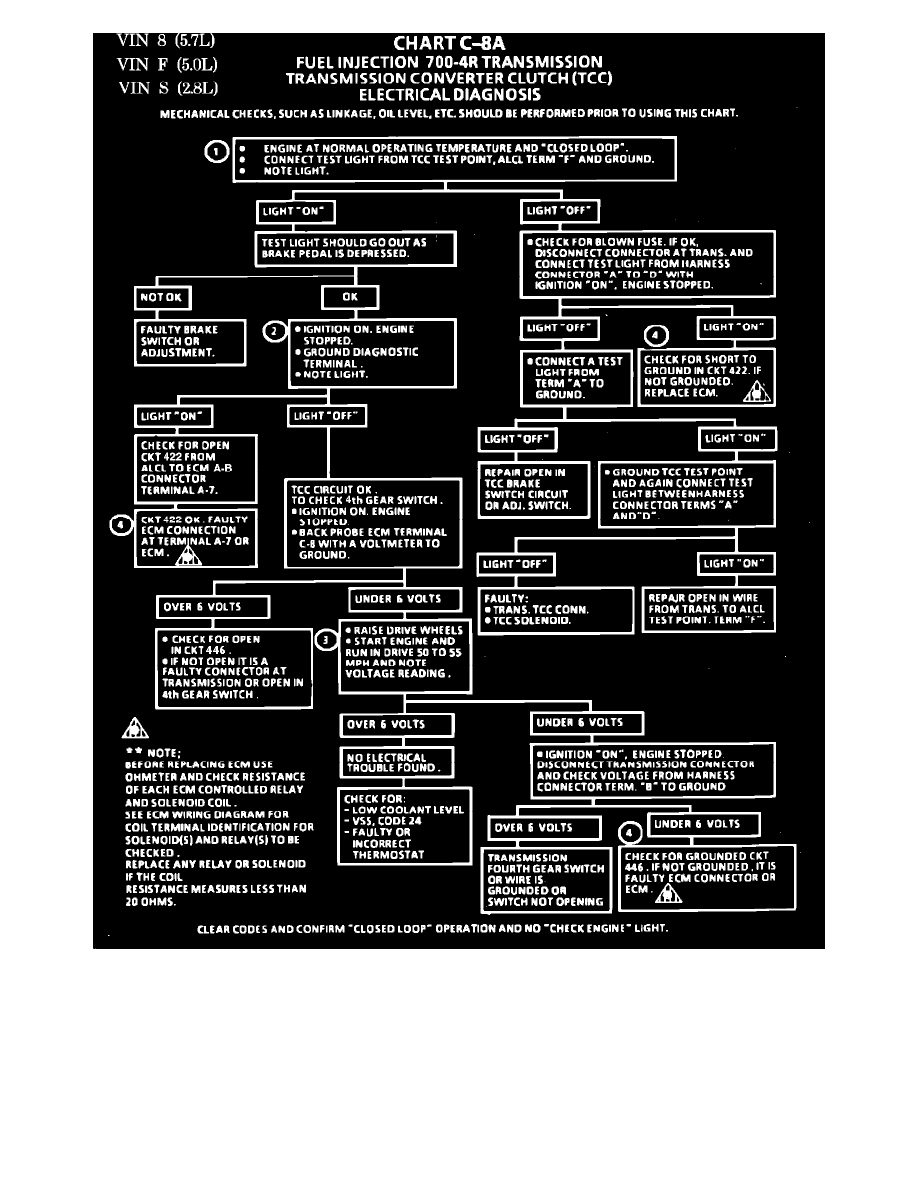
Chart C-8A - Transmission Converter Clutch Electrical Diagnosis
1.
When a test light is connected from ALCL terminal "F" to ground, a test light "ON" indicates battery voltage is OK and the TCC solenoid is
disengaged.
2.
When the diagnostic terminal is grounded, the ECM should energize the TCC solenoid and the test light should go out.
3.
The forth gear switch is normally closed and should open around 50 mph and cause the voltage at ECM terminal C8 to go over 6 volts.
4.
Solenoids are turned "ON" or "OFF" by the ECM internal electronic switches called "drivers". Each driver is part of a group of a group of four
called "Quad-Drivers". Failure of one can damage any other driver within the set. Solenoid coil resistance must measure more than 20 ohms. Less
resistance will cause early failure of the ECM "Driver". Using an ohmmeter, check the coil resistance of solenoids and relays controlled by the
ECM. See ECM wiring diagrams for ECM controlled items.