
Camaro V8-6.2L (2010)
disconnected. Verify that one pair of serial data circuits are greater than 100k ohm.
‹› If each pair of serial data circuits is less than the specified range, replace the control module that was disconnected.
3. Connect the harness connectors at the control module that was disconnected.
4. Disconnect the harness connectors with the mid speed GMLAN serial data circuits at another control module, in the direction of the open circuit.
5. Ignition OFF for 60 seconds, test for greater than 100k ohm between each pair of serial data circuits at the control module connector that was just
disconnected. Verify that one pair of serial data circuits is greater than 100k ohm.
‹› If each pair of serial data circuits is less than the specified range, replace the control module that was just disconnected.
6. Repeat step 3 until one of the following conditions are isolated:
*
An open/high resistance on the serial data circuit between 2 control modules or splice packs, if equipped
*
An open/high resistance on the serial data circuit between a control module and a terminating resistor
*
An open/high resistance terminating resistor
Repair Instructions
Perform the Diagnostic Repair Verification (See: Testing and Inspection/Diagnostic Trouble Code Tests and Associated Procedures/Verification Tests
and Procedures) after completing the repair.
*
GMLAN Wiring Repairs (See: Testing and Inspection/Component Tests and General Diagnostics/General Electrical Diagnostic
Procedures/Wiring Repairs/GMLAN Wiring Repairs)
*
Control Module References (See: Testing and Inspection/Programming and Relearning) for control module replacement, setup, and programming
Scan Tool Does Not Communicate with Low Speed GMLAN Device
Scan Tool Does Not Communicate with Low Speed GMLAN Device
Diagnostic Instructions
*
Perform the Diagnostic System Check - Vehicle (See: Testing and Inspection/Initial Inspection and Diagnostic Overview/Diagnostic System
Check - Vehicle) prior to using this diagnostic procedure.
*
Review Strategy Based Diagnosis (See: Testing and Inspection/Initial Inspection and Diagnostic Overview/Strategy Based Diagnosis) for an
overview of the diagnostic approach.
*
Diagnostic Procedure Instructions (See: Testing and Inspection/Initial Inspection and Diagnostic Overview/Diagnostic Procedure Instructions)
provides an overview of each diagnostic category.
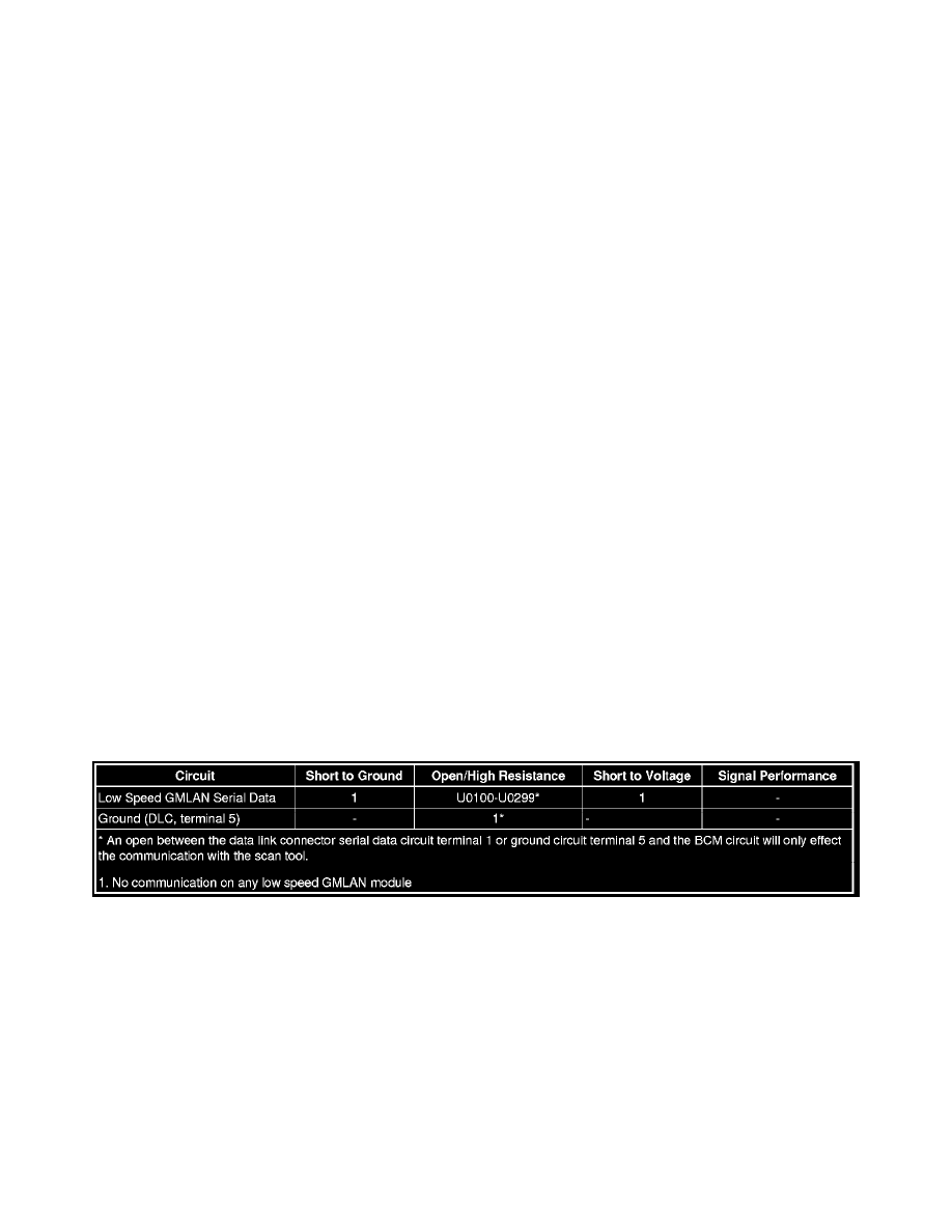
Diagnostic Fault Information
Circuit/System Description
The serial data is transmitted over a single wire to the appropriate control modules. The transmission speed for GMLAN low speed is up to 83.33 Kb/s.
Under normal vehicle operating conditions, the speed of the buss is 33.33 Kb/s. The control modules toggle the serial data circuit between 0-5 V during
normal communications. To wake the control modules connected to the GMLAN low speed serial data circuit, a voltage wake up pulse of 10 V is sent
out. If serial data is lost, control modules will set a no communication code against the non-communicating control module. A loss of serial data
communications DTC does not represent a failure of the module that set it.
Diagnostic Aids
*
Sometimes, while diagnosing a specific customer concern or after a repair, you may notice a history U-code present. However, there is no
associated "current" or "active" status. Loss-of- communication U-codes such as these can set for a variety of reasons. Many times, they are
transparent to the vehicle operator and technician, and/or have no associated symptoms. Eventually, they will erase themselves automatically after
a number of fault-free ignition cycles. This condition would most likely be attributed to one of these scenarios: