
Camaro V8-6.2L (2010)
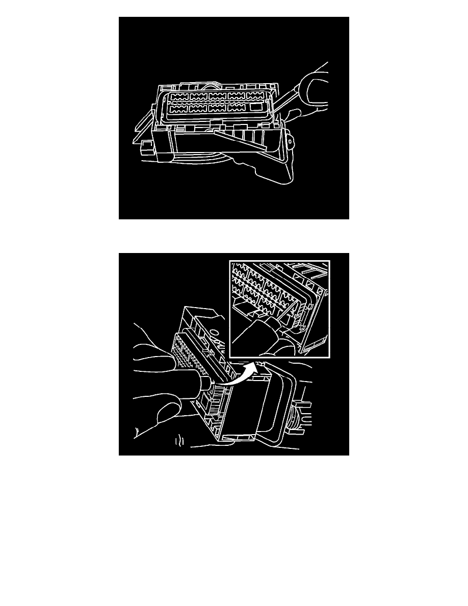
8. Use a small flat-blade tool to pry the other side of the piece to the pre-stage position. If the nose piece is higher than the first step in the nose piece,
gently push down on the nose piece until it meets with resistance from the connector body, you should feel the nose piece click into position.
9. Insert the J-38125-213 into the small terminal release hole on the nose piece and gently pull on the back of the wire.
10. Repair the terminal by following the Repairing Connector Terminals (See: Testing and Inspection/Component Tests and General
Diagnostics/General Electrical Diagnostic Procedures/Connector Repairs/Repairing Connector Terminals) procedure.
11. Insert the repaired terminal back into the cavity. Repeat the diagnostic procedure to verify the repair and reconnect the connector bodies.
Terminated Lead Repair
1. Remove the terminal.
2. Find the appropriate terminated lead.
3. Use the appropriate splice sleeves depending on the gauge size.
4. Refer to Splicing Copper Wire Using Splice Sleeves (See: Testing and Inspection/Component Tests and General Diagnostics/General Electrical
Diagnostic Procedures/Wiring Repairs/Splicing Copper Wire Using Splice Sleeves).
Terminal Insertion Procedure