
Camaro RS V8-305 5.0L VIN E TBI (1990)
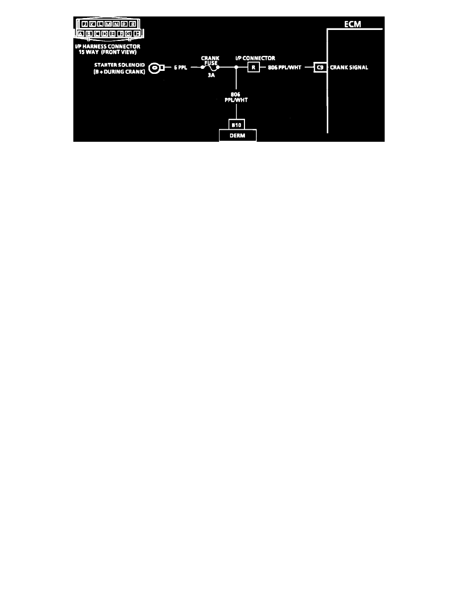
Wiring Diagram For Crank Signal
CIRCUIT DESCRIPTION:
Crank signal is a 12.0 volt signal to the ECM during cranking to allow enrichment and cancel diagnostics until engine is running. The crank signal is also
an input to the Diagnostic Energy Reserve Module (DERM) for the Supplemental Inflatable Restraint (SIR) system. When the DERM senses the engine
is being cranked, it will perform a bulb check on the "INFL REST" light.
TEST DESCRIPTION: The numbers below refer to circled numbers on the diagnostic chart.
1.
Checks for normal (cranking) voltage to terminal "C9" of the ECM. Test light should be "ON" during cranking and then go "OFF" when the
engine is running.
2.
Checks to determine if the source of the blown fuse or fuse link was a faulty ECM. Also, check crank signal to DERM for a short to ground. See
WARNING statement below.
WARNING: This vehicle is equipped with a Supplemental Inflatable Restraint (SIR). See SERVICE PRECAUTIONS for cautions when performing
service on or around SIR components or wiring. Failure to follow Service Precautions may result in an air bag deployment, personal injury, or unneeded
SIR system repair.