
Caprice Wagon V8-305 5.0L (1986)
1. Fill reservoir to indicated full marks inside reservoir with brake fluid as specified on cover. Properly install reservoir cover assembly.
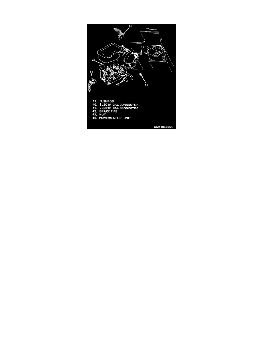
Figure 6 Removing/Installing Brake Pipes
2. Remove brake line connectors from master cylinder outlet ports and allow cylinder to gravity bleed until fluid runs out of the brake line ports.
Reconnect brake lines to master cylinder ports. Tighten connector closest to cowl.
3. Have assistant slowly apply brake pedal to full travel at approximately 50 pounds force (no power assist). Tighten forward brake line connector,
then release pedal fully. Wait 5 seconds. Reapply brake pedal and hold. Open forward connector 1/2 turn to purge air from connector. Tighten
connector, then release brake pedal again.
4. Repeat step 3 until all air is purged from forward connector port. Tighten connector to 14-20 Nm (120-180 in. lb.) Maintain reservoir brake fluid
levels.
5. Repeat steps 3 and 4 except at rear brake line connector.
6. With brake lines, cylinders and master cylinder fully bled, check pedal travel and observe that brake warning indicator does not light during hard
apply.
Pressure
PRESSURE BLEEDING
CAUTION:Pressure bleeding equipment must be of the diaphragm type. It must have a rubber diaphragm between the air supply and the brake fluid to
prevent air, moisture arid other contaminants from entering the hydraulic system.
1. Fill the master cylinder section of reservoir approximately half full with new brake fluid. See fluid specified on reservoir cover.
2. Install the special bleeder adapter J-35360 on Powermaster.
3. Charge bleeder ball to 20-25 psi.
4. Connect line to adapter. Open line valve and depress bleed-off valve on top of adapter until a few drops of fluid appear.
5. Hoist car.
6. Attach bleeder hose to bleeder valve and submerge opposite end in clean container partially filled with brake fluid.
7. Open bleeder valve 1/2 to 3/4 turn and allow fluid to flow until no air is seen in fluid.
8. Bleeding sequence:
a. Right rear
b. Left rear
c. Right front
d. Left front
9. After bleeding, torque brake line connectors to 10-15 lb. ft.
Wheel Bleeding Sequence
WHEEL BLEEDING SEQUENCE
Bleeding Sequence ..................................................................................................................................................................................... RR-LR-RF-LF