
Caprice Wagon V8-350 5.7L VIN P SFI (1996)
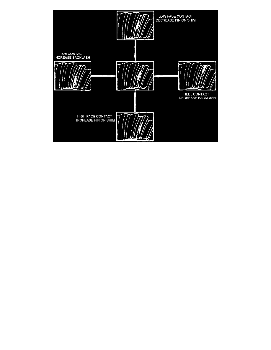
Fig. 7 Front Hub & Wheel Bearing Assembly.
ASSEMBLE
1. Ensure pinion depth and bearing preload are properly adjusted, as described under Adjustments. See: Pinion Gear/Adjustments
2. Install differential case assembly and selected side bearing shims as described under Adjustments. See: Pinion Gear/Adjustments
3. Install bearing caps in proper position and torque cap bolts to 55 ft. lbs.
4. Rotate assembly to ensure bearings are properly seated.
5. Mount dial indicator on housing with plunger bearing against tooth on ring gear, Fig. 15. Use small contact button on indicator plunger so that
contact can be made at heel end of tooth and position dial indicator with plunger inline with gear rotation and perpendicular to gear tooth.
6. Hold pinion stationary and rock ring gear back and forth while reading backlash on indicator.
7. Check backlash at three evenly spaced positions around ring gear and record readings. If backlash varies by more than 0.002 inch at any
position, check ring gear installation and runout, and correct as needed.
8. If backlash is not within specifications, remove differential case assembly and bearing shims keeping shims in order.
9. Backlash is adjusted by increasing thickness of one shim while decreasing thickness of opposite side shim by the same amount in order to maintain
proper side bearing preload. Select shims to adjust backlash as follows:
a. If backlash is excessive, increase thickness of shim on gear tooth side and decrease thickness of shim on opposite side by the same amount.
b. If backlash is less than specified, decrease thickness of shim on gear tooth side while increasing thickness of opposite shim by the same
amount. Each 0.002 inch change in shim thickness alters backlash by 0.001 inch.
10. Reinstall differential assembly, shims and bearing caps, torque bearing cap bolts to 55 ft. lbs., then recheck backlash and adjust as needed.
11. If side bearing preload was set to zero during side bearing preload adjustment, proceed as follows:
a. Remove both bearing caps and shim packs, keeping shim packs in respective left or right positions.
b. Select left side differential preload shim from specifications chart and insert shim between left bearing race and spacer, then install left bearing
cap with bolts hand tight.
c. Select right side differential preload shim from specifications chart and insert shim between right bearing race and spacer using a soft faced
hammer.
d. Install right bearing cap and torque all cap bolts to 55 ft. lbs.
12. Ensure ring gear teeth are clean and free from oil, then coat both drive and coast side of each tooth with marking compound.
13. Apply braking force to load ring gear, then rotate driveshaft yoke with wrench so that ring gear rotates one full revolution in each direction. Test
made without loading gears will not yield satisfactory pattern, excessive rotating of gears is not recommended.
14. Compare gear tooth pattern with Fig. 16, and correct assembly adjustments as needed.
15. When proper gear tooth contact pattern has been obtained, clean marking compound from gears.
16. Install axles and driveshaft. Refer to Drive/Propeller Shafts, Bearings and Joints for procedures. See: Drive/Propeller Shafts, Bearings and
Joints/Drive/Propeller Shaft/Service and Repair
17. Install rear cover using RTV or new gasket and torque cover bolts to 20 ft. lbs., then fill rear axle with appropriate lubricant.
18. On models equipped with limited slip differential, add additive No. 1050428 or equivalent to rear axle lubricant.