
Celebrity V6-191 3.1L (1990)
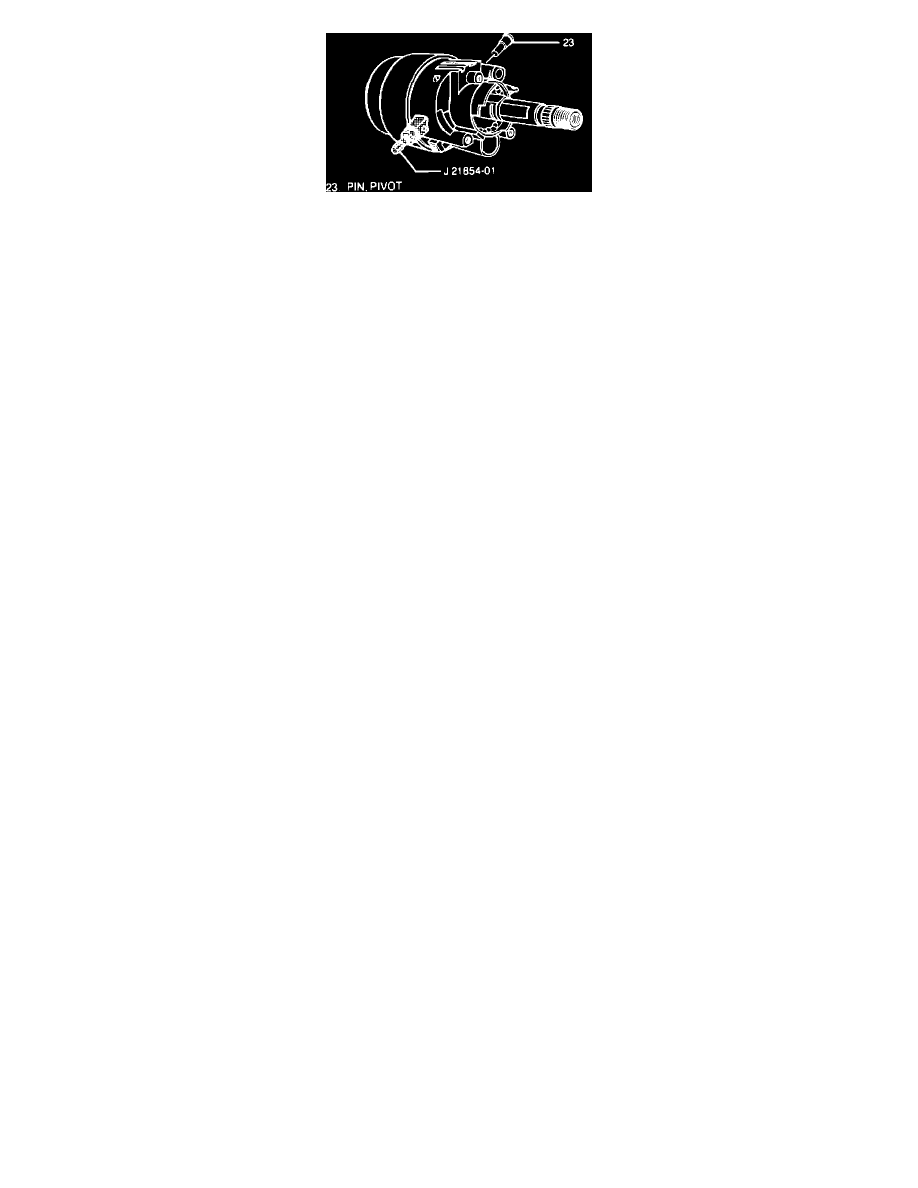
Fig. 63 Removing Pivot Pins
1.
Remove shaft lock, turn signal cancelling cam, upper bearing spring, upper bearing seat, inner race, turn signal switch, alarm assembly & lock
cylinder set, lock housing cover, cover end cap, pivot & pulse switch assembly, dimmer switch rod actuator & tilt spring assembly as previously
described.
2.
Remove pivot pins using special tool No. J 21854-01 or equivalent, Fig. 63.
3.
Reinstall tilt lever and remove column housing by pulling back on tilt lever and pulling housing down and away from column.
4.
Remove driveshaft, switch actuator sector, switch actuator rack and rack preload spring.
5.
Remove release lever pin, shoe release lever and release lever spring.
6.
Remove dowel pin, lock shoes, shoe springs and bearing assembly.
7.
Remove hex head screw, lock bolt spring and lock bolt.
Assembly
1.
Install bearing assembly to column housing.
2.
Install driveshaft, switch actuator sector and lock shoes.
3.
Install dowel pin, shoe springs and release lever spring.
4.
Install shoe release lever, release lever pin and rack preload spring.
5.
Install switch actuator rack to switch actuator sector.
6.
Install lock bolt, lock bolt spring and hex head screw. Torque screw to 37 inch lbs.
7.
Install column housing to column. Position column housing and align switch actuator rack with pin on end of actuator assembly. pull back on tilt
lever, pushing column housing onto column housing support assembly. Release tilt lever to lock shoes onto dowel pins.
8.
Remove tilt lever and install pivot pins lubricated with lithium grease.
9.
Perform assembly steps for shaft lock, turn signal cancelling cam, upper bearing spring, upper bearing seat, inner race, turn signal switch, alarm
assembly & lock cylinder set, lock housing cover, cover end cap, pivot & pulse switch assembly, dimmer switch rod actuator & tilt spring
assembly as previously described.
SHAFT ASSEMBLY, COLUMN HOUSING SUPPORT, SHIFT TUBE ASSEMBLY, IGNITION SWITCH, DIMMER SWITCH & LOWER
BEARING ASSEMBLY
Disassembly
1.
Remove shaft lock, turn signal cancelling cam, upper bearing spring, upper bearing seat, inner race, turn signal switch, alarm assembly & lock
cylinder set, lock housing cover, cover end cap, pivot & pulse switch assembly, dimmer switch rod actuator & tilt spring assembly, column
housing, lock shoes, actuator sector assembly, switch actuator rack, bearings & lock bolt assembly as previously described.
2.
Remove column from vehicle.
3.
Remove bearing and seal retainer, lower spring retainer, lower bearing spring and lower bearing seat.
4.
Remove hex head screws, adapter and bearing assembly.
5.
Remove column shaft assembly and inspect for accident damage.
6.
Mark upper and lower shaft assemblies to ensure proper assembly.
7.
Remove upper shaft assembly, lower shaft assembly. Tilt 90° to each other and disengage.
8.
Remove centering sphere from upper shaft assembly. Rotate sphere 90° and slip out.
9.
Remove joint preload spring from centering sphere.
10.
Remove screws, column housing support assembly and dimmer switch rod from steering column jacket assembly.
11.
Remove rod from column housing support assembly and screws and shift lever gate from support assembly.
12.
Remove hex nut, screw, dimmer switch assembly and mounting stud.
13.
Remove ignition switch assembly and switch actuator assembly.
14.
Remove switch actuator assembly from switch assembly.
15.
Remove shift tube retaining ring, thrust washer and shift lever spring.
16.
Remove shift tube using special tool No. J 23072 or equivalent.
17.
Remove lock plate, wave washer and gearshift lever bowl.
Assembly
1.
Install shift lever spring to gear shift lever bowl and gear shift lever bowl to shift tube jacket.
2.
Install wave washer lubricated with lithium grease and lock plate.
3.
Install shift tube using special tool No. J 23073 or equivalent.
4.
Install thrust washer and shift tube retaining ring.