
Citation II L4-151 2.5L VIN R TBI (1984)
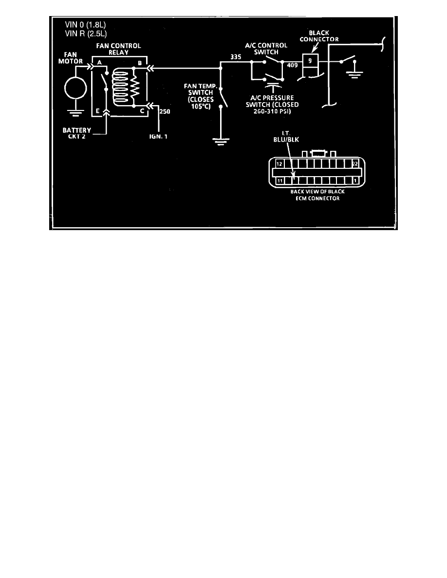
Fig. 087 - Wiring Diagram for Chart C-12 Cooling Fan Control Circuit. VIN 0, VIN R
CHART C-12, FAN CONTROL CIRCUIT
Battery voltage is supplied to the fan relay on terminal "D" and ignition to terminal "C".
Grounding relay terminal "B" will close relay and supply battery voltage to the fan motor.
Above 30 MPH the ECM will remove the ground from CKT 409. If the coolant temperature and A/C pressure switches are open the fan will stop.
a.
ECM control
-
A/C on
-
Engine running
-
Vehicle speed less than 35 MPH
-
CKT 335, 409 and relay terminal "B" grounded by ECM C-D connector terminal C1
-
Coolant temperature less than 110 to 115°C
b.
Coolant temperature control
-
Coolant above 110°C to 115°C
-
Temperature switch closed to ground
-
CKT 335 and relay terminal "B" grounded
c.
A/C pressure control
-
A/C high side pressure above 260 to 310 psi.
-
A/C pressure switch closed to ground.
-
CKT 335 and relay terminal "B" grounded
Solenoids and relays are turned "ON" or "OFF" by the ECM internal electronic switches called "drivers". Each driver is part of a group of four called
"Quad-Drivers". Failure of one can damage any other driver within the set.
Solenoid or relay coil resistance must measure more than 20 ohms. Less resistance will cause early failure of the ECM "DRIVER". Using an
ohmmeter, check the coil resistance of the following before installing a replacement ECM.
d.
A/C Relay.