
Cobalt L4-2.0L SC VIN P (2005)
Tighten
Tighten the shaft collar screw to 19 Nm (14 lb ft).
9. Place EN 45680-861 onto the cylinder to be trimmed with the directional arrow (1) pointing in line with the crankshaft centerline and the front of
the block.
10. Install the 4 EN 45680-864 (2) into the cylinder head bolt holes in the block.
Tighten
Tighten the bolts progressively to 20 Nm (15 lb ft).
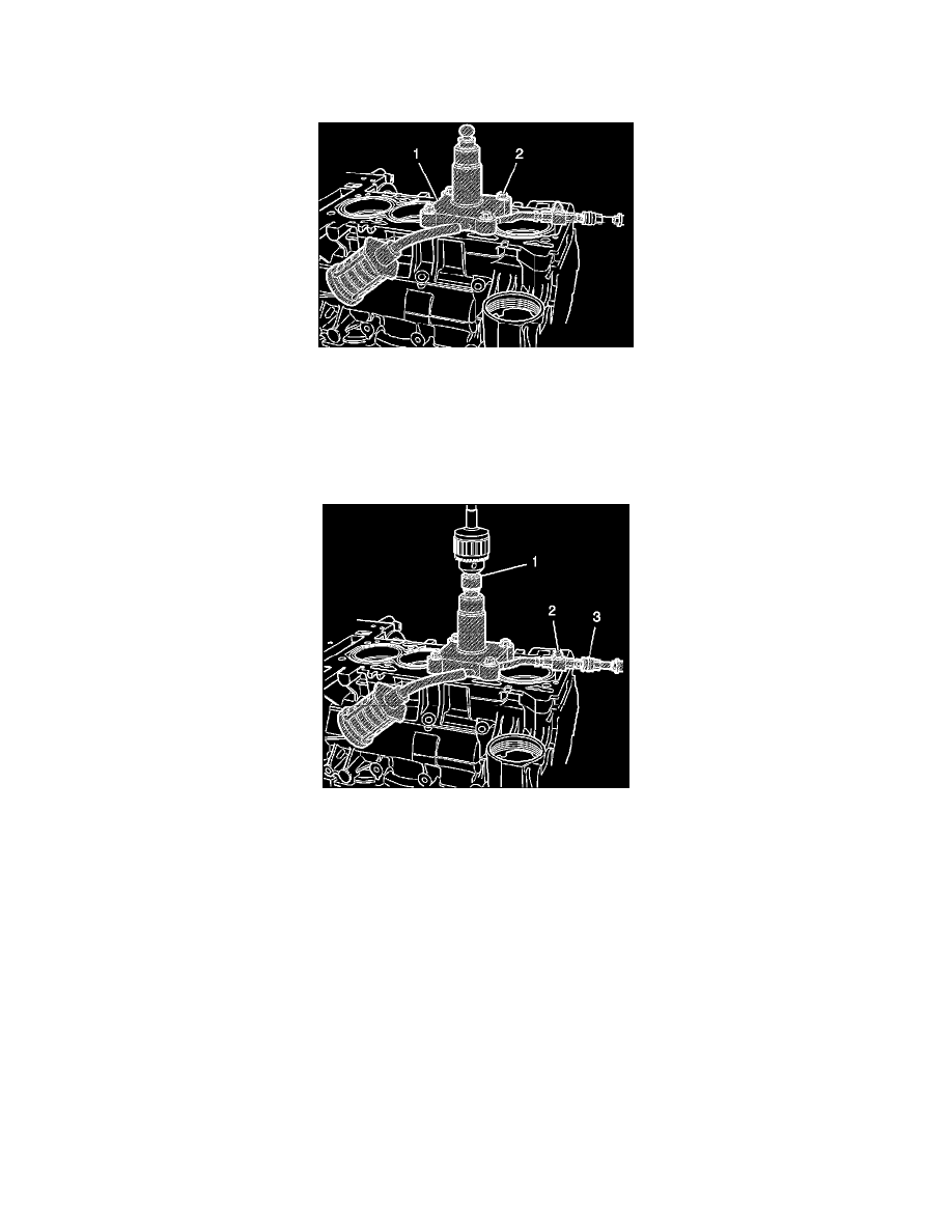
11. Fasten EN 45680-866 (1) into the drill chuck.
Note: Ensure there are no kinks in the air feed hose or the vacuum hose. Kinks in the hose may cause metal shavings to exit the cutting tool in any
direction, which can cause possible engine damage.
12. Connect a compressed air supply (75-125 psi) (517-862 kpa) to the male quick connect (3) located on EN 45680-861. Turn the compressed air
valve (2) to the open position. This starts the venturi vacuum system that will catch the metal shavings.
13. Place EN 45680-866/drill (1) vertically onto the ball end of EN 45680-861. Do not apply downward force on the drill until the full rotational
speed has been reached. After reaching full rotational speed, gradually apply downward force until the cutting action is complete - approximately
10 seconds.
14. Remove EN 45680-866 (1) from the EN 45680-861.
15. Turn off the compressed air valve (2).
16. Remove EN 45680-861 from the engine block.
17. Remove any material shavings that may be found resting on the EN 45680-863.
18. Remove EN 45680-863 and wipe the cylinder bore and surrounding areas free from any powder residue.
19. Proceed to the next cylinder bore sleeve to be trimmed repeating steps 6-14.